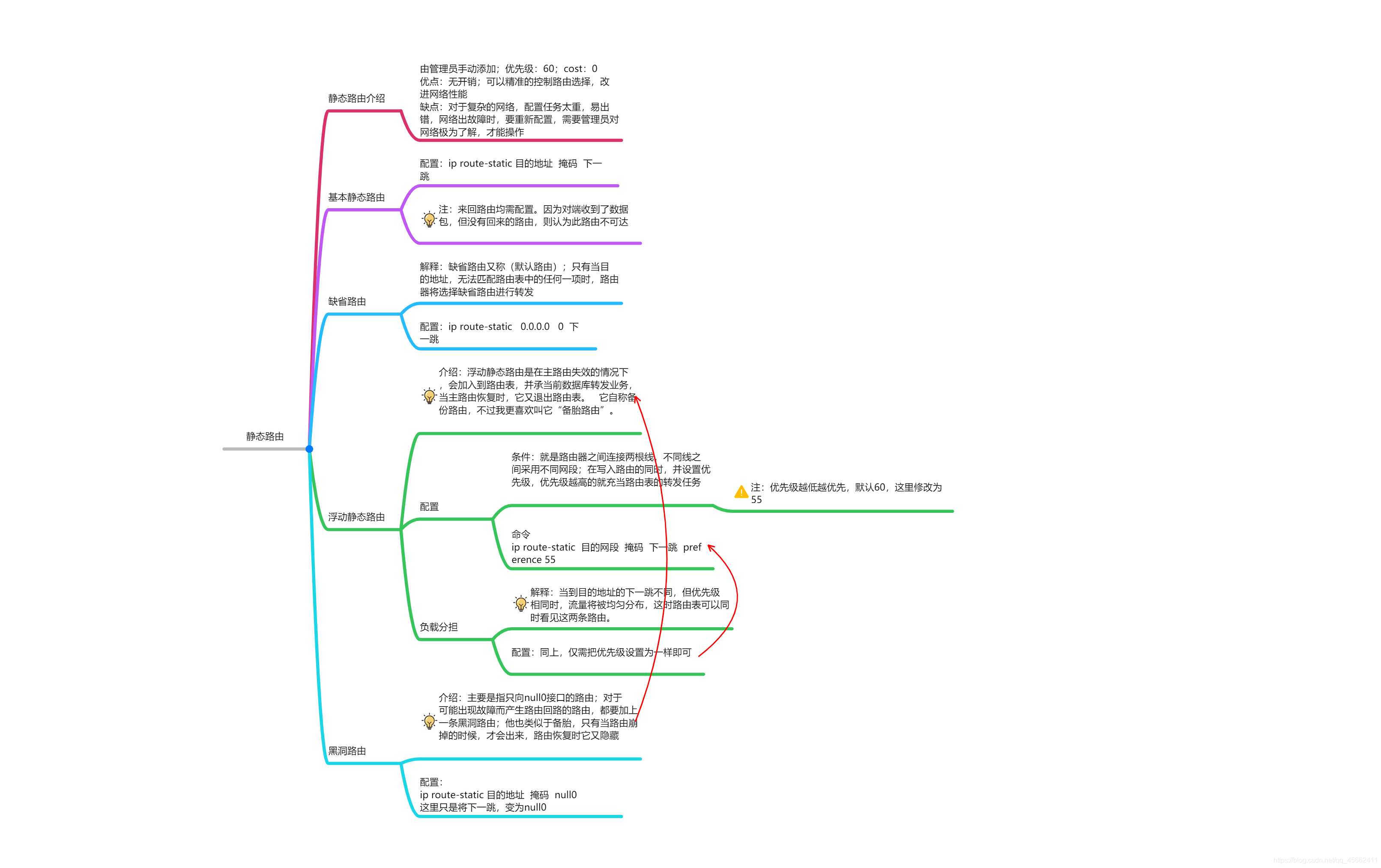
实操
基本路由配置
组网方式
实验目的:使R1的1.1.1.1和R2的2.2.2.2之间能够通信
R1配置:
[R1]int loop 0
[R1-LoopBack0]ip ad 1.1.1.1 24
[R1-LoopBack0]int g0/0
[R1-GigabitEthernet0/0]ip ad 192.168.1.1 24
[R1]ip route-static 2.2.2.0 24 192.168.1.2
R2配置:
[R2]int loop 0
[R2-LoopBack0]ip ad 2.2.2.2 24
[R2-LoopBack0]int g0/0
[R2-GigabitEthernet0/0]ip ad 192.168.1.2 24
[R2]ip route-static 1.1.1.0 24 192.168.1.1
这时,我们可以在R1或者R2上使用这条命令查看路由表中是否含有这条路由,我这在R1上查看
[R1]dis ip routing-table
2.2.2.0/24 Static 60 0 192.168.1.2 GE0/0
有这条路由信息,说明配置成功了
缺省路由
我们还是利用基础路由配置的图,现在我要配置缺省路由使1.1.1.1能与2.2.2.2通信
1、我们要删除原来的路由,可以是用undo这条命令
[R1]undo ip route-static 2.2.2.0 24 192.168.1.2
[R2]undo ip route-static 1.1.1.0 24 192.168.1.1
2、现在我们可以在R1、R2上添加这条路由让其实现通信
[R1]ip ro 0.0.0.0 0 192.168.1.2
[R2]ip ro 0.0.0.0 0 192.168.1.1
3、现在我们在R2查看路由表项时,可以看见这条路由信息
0.0.0.0/0 Static 60 0 192.168.1.1 GE0/0
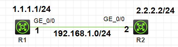
浮动静态路由
组网方式:
R1配置:
[R1]int loop0
[R1-LoopBack0]ip ad 1.1.1.1 24
[R1-LoopBack0]int g0/0
[R1-GigabitEthernet0/0]ip ad 192.168.1.1 24
[R1-GigabitEthernet0/0]int g0/1
[R1-GigabitEthernet0/1]ip ad 192.168.2.1 24
[R1]ip route-static 2.2.2.0 24 192.168.1.2
[R1]ip route-static 2.2.2.0 24 192.168.2.2
R2配置:
[R2]int loop 0
[R2-LoopBack0]ip ad 2.2.2.2 24
[R2-LoopBack0]int g0/0
[R2-GigabitEthernet0/0]ip ad 192.168.1.2 24
[R2-GigabitEthernet0/0]int g0/1
[R2-GigabitEthernet0/1]ip ad 192.168.2.2 24
[R2]ip route-static 1.1.1.0 24 192.168.1.1
[R2]ip route-static 1.1.1.0 24 192.168.2.1
此时我们查看路由表时,可以看到这条信息
2.2.2.0/24 Static 60 0 192.168.1.2 GE0/0
192.168.2.2 GE0/0
这就是我们浮动静态路由中的负载分担
如何设置成浮动静态路由呢?只需要在写入的路由后面加上preference即可;我们这里就将192.168.1.0网段的路由设置为主路由
演示:
[R1]ip route-static 2.2.2.0 24 192.168.2.2 preference 55
[R2]ip route-static 1.1.1.0 24 192.168.1.1 preference 55
这时我们查看R1路由表时,就只有这条优先级为55的路由了
2.2.2.0/24 Static 55 0 192.168.2.2 GE0/1
当着条路由崩掉的时候,备份路由会自动浮现
黑洞路由
我们都知道实际网络不可能这么简单,但我们做实验,就依据基本路由的图来此次实验,为了防止路由1.1.1.0崩掉,而造成路由环路,所以我们写一条黑洞路由。
配置:
[R2]ip route-static 1.1.1.0 24 NULL 0
网络正常情况下,此路由会隐藏,当网络出故障时,会启用。
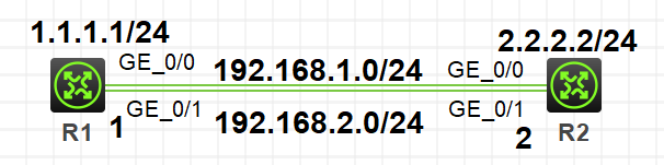
一张图高懂华三静态路由及其衍生路由
猜你喜欢
转载自blog.csdn.net/qq_45662411/article/details/105326302
周排行