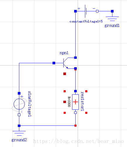
如下图所示的电路,只能在正半周导通。
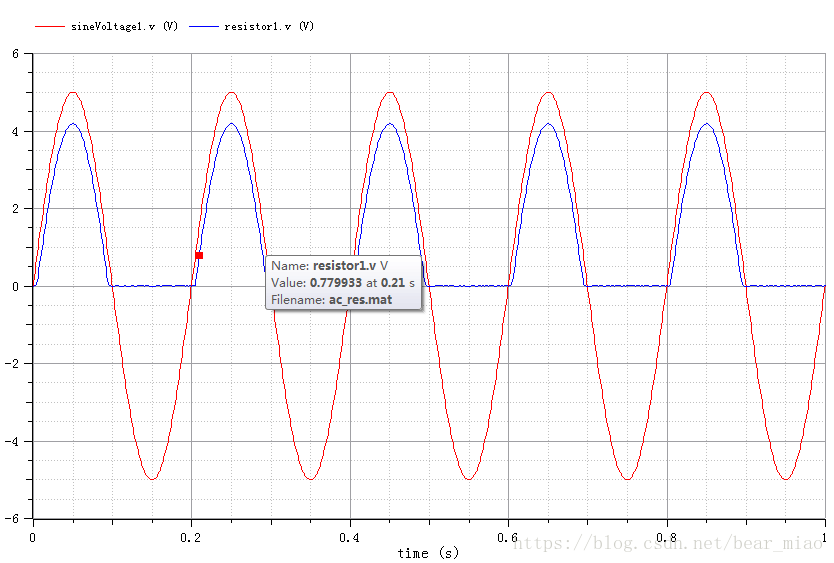
曲线如下图所示
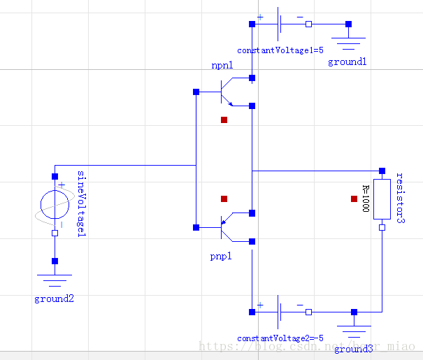
有一种方法可以使整个周期的信号得到放大,急救室采用两个互补对称的晶体管,如一对匹配的npn/pnp BJT或者一对匹配的n沟道/p沟道FET。这两个晶体管分别在输入信号的正半周期和负半周期导通。
电路
Modelica.Electrical.Analog.Sources.SineVoltage sineVoltage1(V = 5, freqHz = 5)
曲线
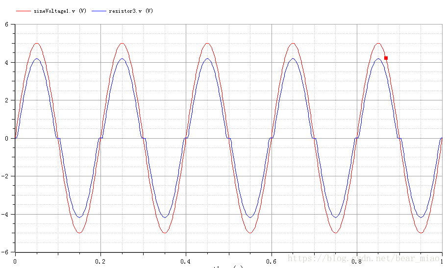
当基极电压为零时,输入信号幅值必须大于VBE才能使晶体管导通。结果是在输入信号正负交替的一个时间间隔内,两个晶体管都不导通。此时在输出波形上产生的失真叫交越失真。
程序
model ac
Modelica.Electrical.Analog.Sources.ConstantVoltage constantVoltage1(V = 5) annotation(
Placement(visible = true, transformation(origin = {8, 16}, extent = {{-10, -10}, {10, 10}}, rotation = 0)));
Modelica.Electrical.Analog.Basic.Ground ground1 annotation(
Placement(visible = true, transformation(origin = {32, 6}, extent = {{-10, -10}, {10, 10}}, rotation = 0)));
Modelica.Electrical.Analog.Semiconductors.NPN npn1 annotation(
Placement(visible = true, transformation(origin = {-12, -8}, extent = {{-10, -10}, {10, 10}}, rotation = 0)));
Modelica.Electrical.Analog.Sources.SineVoltage sineVoltage1(V = 5, freqHz = 5) annotation(
Placement(visible = true, transformation(origin = {-72, -48}, extent = {{-10, -10}, {10, 10}}, rotation = -90)));
Modelica.Electrical.Analog.Basic.Ground ground2 annotation(
Placement(visible = true, transformation(origin = {-72, -78}, extent = {{-10, -10}, {10, 10}}, rotation = 0)));
Modelica.Electrical.Analog.Basic.Resistor resistor3(R = 1000) annotation(
Placement(visible = true, transformation(origin = {44, -46}, extent = {{-10, -10}, {10, 10}}, rotation = -90)));
Modelica.Electrical.Analog.Sources.ConstantVoltage constantVoltage2(V = -5) annotation(
Placement(visible = true, transformation(origin = {8, -86}, extent = {{-10, -10}, {10, 10}}, rotation = 0)));
Modelica.Electrical.Analog.Basic.Ground ground3 annotation(
Placement(visible = true, transformation(origin = {34, -96}, extent = {{-10, -10}, {10, 10}}, rotation = 0)));
Modelica.Electrical.Analog.Semiconductors.PNP pnp1 annotation(
Placement(visible = true, transformation(origin = {-12, -56}, extent = {{-10, 10}, {10, -10}}, rotation = 0)));
equation
connect(constantVoltage1.n, ground1.p) annotation(
Line(points = {{18, 18}, {32, 18}, {32, 18}, {32, 18}}, color = {0, 0, 255}));
connect(constantVoltage1.p, npn1.C) annotation(
Line(points = {{-2, 18}, {-2, -5}}, color = {0, 0, 255}));
connect(sineVoltage1.p, npn1.B) annotation(
Line(points = {{-72, -38}, {-72, -38}, {-72, -34}, {-22, -34}, {-22, -8}, {-22, -8}}, color = {0, 0, 255}));
connect(npn1.B, pnp1.B) annotation(
Line(points = {{-22, -8}, {-22, -8}, {-22, -56}, {-22, -56}}, color = {0, 0, 255}));
connect(resistor3.p, pnp1.E) annotation(
Line(points = {{44, -36}, {-2, -36}, {-2, -52}, {-2, -52}}, color = {0, 0, 255}));
connect(npn1.E, pnp1.E) annotation(
Line(points = {{-2, -13}, {-2, -52}}, color = {0, 0, 255}));
connect(pnp1.C, constantVoltage2.p) annotation(
Line(points = {{-2, -64}, {-2, -64}, {-2, -86}, {-2, -86}}, color = {0, 0, 255}));
connect(resistor3.n, ground3.p) annotation(
Line(points = {{44, -56}, {44, -56}, {44, -86}, {34, -86}, {34, -86}}, color = {0, 0, 255}));
connect(ground3.p, constantVoltage2.n) annotation(
Line(points = {{34, -86}, {18, -86}, {18, -86}, {18, -86}}, color = {0, 0, 255}));
connect(sineVoltage1.n, ground2.p) annotation(
Line(points = {{-72, -58}, {-72, -58}, {-72, -68}, {-72, -68}}, color = {0, 0, 255}));
annotation(
uses(Modelica(version = "3.2.2")));
end ac;