1. First explain what the ADC_SQRx register does?
Answer: A popular and non-strict understanding is to set the priority of the conversion order of all your ADC channels.
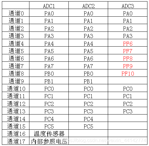
2. Let me talk about what is the content of the ADC_SQRx register Zhongtian?
Answer: Fill in the number of the conversion channel (0~17). Because there are a total of 18 channels and they are numbered 0-17
3. Examples to illustrate:
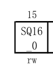
(1) ADC1->SQR1& = 0<<16
Fill 0 into the 16th bit of SQR1, that is, fill the number 0 (ie channel 0) into the 16th conversion position, so that the conversion of channel 0 is placed At the end.
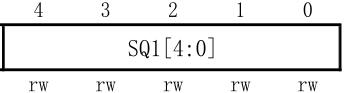
 (2) ADC1->SQR3 |=1<<0
Fill 1 in the first digit of SQR1, that is, fill the number 1 (that is, channel 1) into the position of the first conversion, so that the conversion of channel 1 is Put it first.
4. ADC's own learning:
(1) STM32 ADC is a 12-bit successive approximation analog-to-digital converter.
It has 18 channels and can measure 16 external and 2 internal signal sources.
(2) Channel A/D conversion can be executed in single, continuous, scan or discontinuous mode.
Use ADC1 to rule the channel sequence as CH0, CH1, CH2, CH3,
do not start SCAN mode
① In single conversion mode:
start ADC1, Then start to convert CH0 (the first channel of ADC_SQR) and stop after the conversion is completed, wait for the next ADC start , and continue to convert from ch0
②In continuous conversion mode:
start ADC1, then start to convert CH0 (the first channel of ADC_SQR) conversion After completion, return to the first step and continue to convert ch0
Start in SCAN mode
①In single conversion mode:
start ADC1, then
1. Start to convert CH0,
2. Automatically start to convert CH1 after the conversion is completed
3. Automatically start to convert CH2 after the conversion is completed
4. Automatically start to convert CH3 after the conversion is completed
5. After the conversion is completed, stop, wait for the next ADC start and start the conversion from ch0 after the next ADC start
②In continuous conversion mode:
Start ADC1, then
1. Start to convert CH0
2. Automatically start to convert CH1 after the conversion is completed
3. Automatically start to convert CH2 after the conversion is completed
4. Automatically start to convert CH3 after the conversion is completed
5. After the conversion is completed, return to the first step and continue to convert from ch0
(3) The ADC result can be left-justified or right-justified and stored in the 16-bit data register. This can be set.
(4) The analog watchdog feature allows the application to detect whether the input voltage exceeds the user-defined high/low threshold.
(5) Do not let the ADC clock exceed 14M, otherwise the accuracy of the result will decrease.
(6) STM32 divides ADC conversion into 2 channel groups: regular channel group and injection channel group.
(7) A series of conversions in any order on any number of channels constitute a group conversion. For example, the conversion can be done in the following order: channel 3, channel 8, channel 2, channel 2, channel 0, channel 2, channel 2, channel 15.
(8) The injection channel can have trigger injection: for example, external event trigger (timer capture, EXTI line, etc.) and software source trigger event (triggered by a certain bit of the register)
automatic injection (set the JAUTO bit, after the regular group channel, inject Group channels are automatically converted.)
(9) Channel sampling time can be set through registers
(10) Interrupts are generated when conversion ends, injection conversion ends, and analog watchdog events occur