가이드
이 기사는 주로 EdgeDrawing 모듈을 사용하여 OpenCV에서 원을 찾는 방법을 소개합니다(자세한 단계 + 코드).
배경 소개
OpenCV4.5.2부터 오픈 소스 라이브러리 ED_Lib는 Contrib 모듈에 캡슐화되어 이미지에서 직선, 선분, 타원 및 원을 찾습니다. Github 주소:
https://github.com/CihanTopal/ED_Lib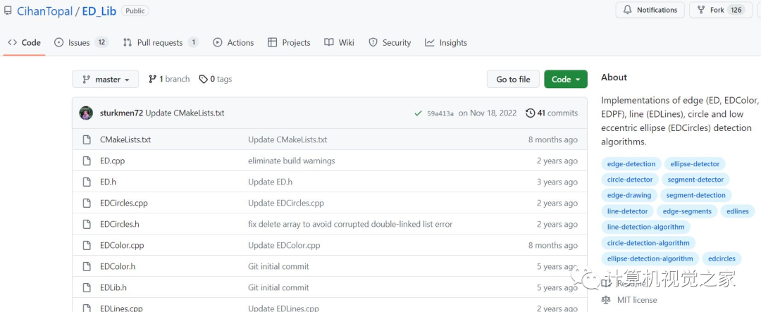
알고리즘 원리 소개:
에지 드로잉(ED) 알고리즘은 에지 감지 문제에 대한 적극적인 접근 방식입니다. 빼기 방식(즉, 이미지에 그라디언트 필터를 적용한 후 Canny의 비최대 억제 및 히스테리시스와 같은 여러 규칙에 따라 픽셀이 제거됨)을 따르는 기존의 다른 많은 에지 감지 알고리즘과 달리 ED 알고리즘은 다음을 채택합니다. 추가 전략 작업은 가장자리 픽셀을 하나씩 선택하는 것이므로 "가장자리 그리기"라고 합니다. 그런 다음 이러한 무작위 모양의 가장자리 세그먼트를 처리하여 더 높은 수준의 가장자리 기능, 즉 선, 원, 타원 등을 추출합니다. 임계값 기울기 크기에서 가장자리 픽셀을 추출하는 인기 있는 방법은 각 픽셀이 기울기 방향을 따라 최대 기울기 응답을 갖는지 여부를 테스트하고 그렇지 않은 경우 제거하는 비최대 억제입니다. 그러나 이 방법은 인접 픽셀의 상태를 확인하지 않으므로 가장자리 조각의 품질이 낮을 수 있습니다(가장자리 연속성, 부드러움, 얇음, 위치 지정 측면). 비최대 억제 대신 ED는 일련의 에지 픽셀을 대상으로 하여 에지 세그먼트의 전체 그래디언트 응답을 최대화하여 연결합니다. 따라서 추가적인 lag step 없이 고품질의 edge fragment를 추출할 수 있습니다.
OpenCV에서 사용되는 소개 문서:
https://docs.opencv.org/4.5.2/d1/d1c/classcv_1_1ximgproc_1_1EdgeDrawing.html
사용 단계
EdgeDrawing 클래스는 Contrib의 ximgproc 모듈에 있으며 C++에서 사용하려면 다음 조건을 충족해야 합니다.
① OpenCV >= 4.5.2
② CMake는 Contrib 모듈을 컴파일합니다.
③ edge_drawing.hpp 헤더 파일 포함
Python에서 사용하려면 opencv-python-contrib >=4.5.2를 설치해야 합니다.
[1] Python 데모:
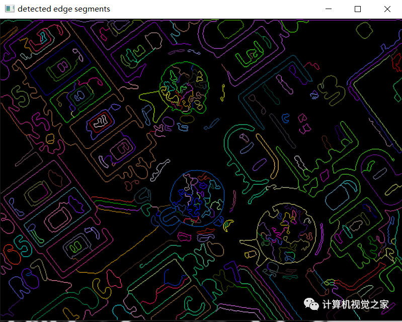
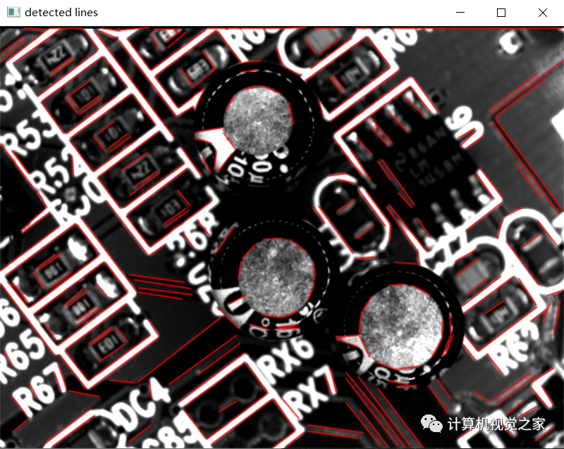
#公众号--计算机视觉之家'''This example illustrates how to use cv.ximgproc.EdgeDrawing class.Usage:ed.py [<image_name>]image argument defaults to board.jpg'''# Python 2/3 compatibilityfrom __future__ import print_functionimport numpy as npimport cv2 as cvimport random as rngimport sysrng.seed(12345)def main():try:fn = sys.argv[1]except IndexError:fn = 'board.jpg'src = cv.imread(cv.samples.findFile(fn))gray = cv.cvtColor(src, cv.COLOR_BGR2GRAY)cv.imshow("source", src)ssrc = src.copy()*0lsrc = src.copy()esrc = src.copy()ed = cv.ximgproc.createEdgeDrawing()# you can change parameters (refer the documentation to see all parameters)EDParams = cv.ximgproc_EdgeDrawing_Params()EDParams.MinPathLength = 50 # try changing this value between 5 to 1000EDParams.PFmode = False # defaut value try to swich it to TrueEDParams.MinLineLength = 20 # try changing this value between 5 to 100EDParams.NFAValidation = True # defaut value try to swich it to Falseed.setParams(EDParams)# Detect edges# you should call this before detectLines() and detectEllipses()ed.detectEdges(gray)segments = ed.getSegments()lines = ed.detectLines()ellipses = ed.detectEllipses()#Draw detected edge segmentsfor i in range(len(segments)):color = (rng.randint(0,256), rng.randint(0,256), rng.randint(0,256))cv.polylines(ssrc, [segments[i]], False, color, 1, cv.LINE_8)cv.imshow("detected edge segments", ssrc)#Draw detected linesif lines is not None: # Check if the lines have been found and only then iterate over these and add them to the imagelines = np.uint16(np.around(lines))for i in range(len(lines)):cv.line(lsrc, (lines[i][0][0], lines[i][0][1]), (lines[i][0][2], lines[i][0][3]), (0, 0, 255), 1, cv.LINE_AA)cv.imshow("detected lines", lsrc)#Draw detected circles and ellipsesif ellipses is not None: # Check if circles and ellipses have been found and only then iterate over these and add them to the imagefor i in range(len(ellipses)):center = (int(ellipses[i][0][0]), int(ellipses[i][0][1]))axes = (int(ellipses[i][0][2])+int(ellipses[i][0][3]),int(ellipses[i][0][2])+int(ellipses[i][0][4]))angle = ellipses[i][0][5]color = (0, 0, 255)if ellipses[i][0][2] == 0:color = (0, 255, 0)cv.ellipse(esrc, center, axes, angle,0, 360, color, 2, cv.LINE_AA)cv.imshow("detected circles and ellipses", esrc)cv.waitKey(0)print('Done')if __name__ == '__main__':print(__doc__)main()cv.destroyAllWindows()
실행 명령: ed.py [<이미지_이름>]
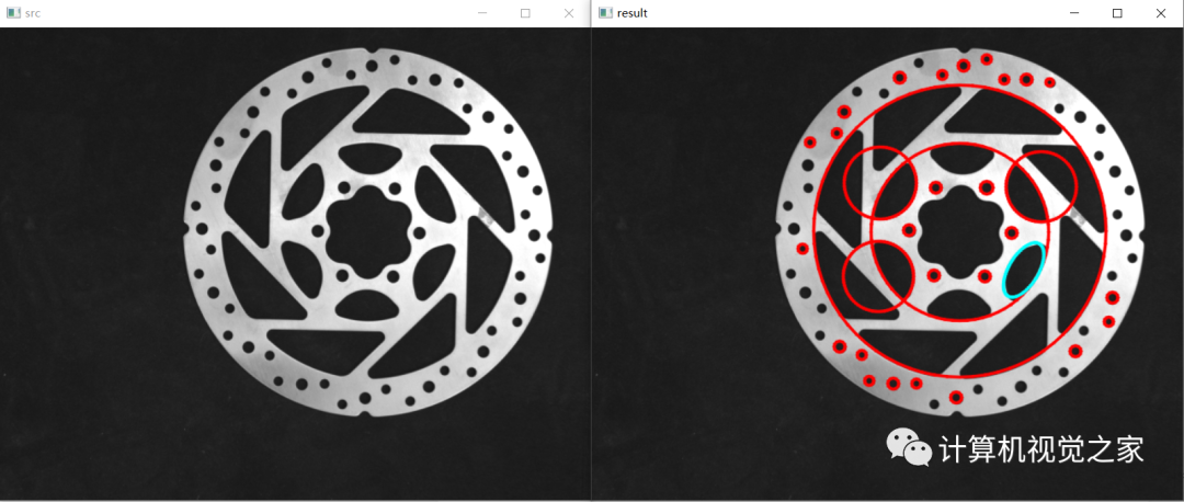
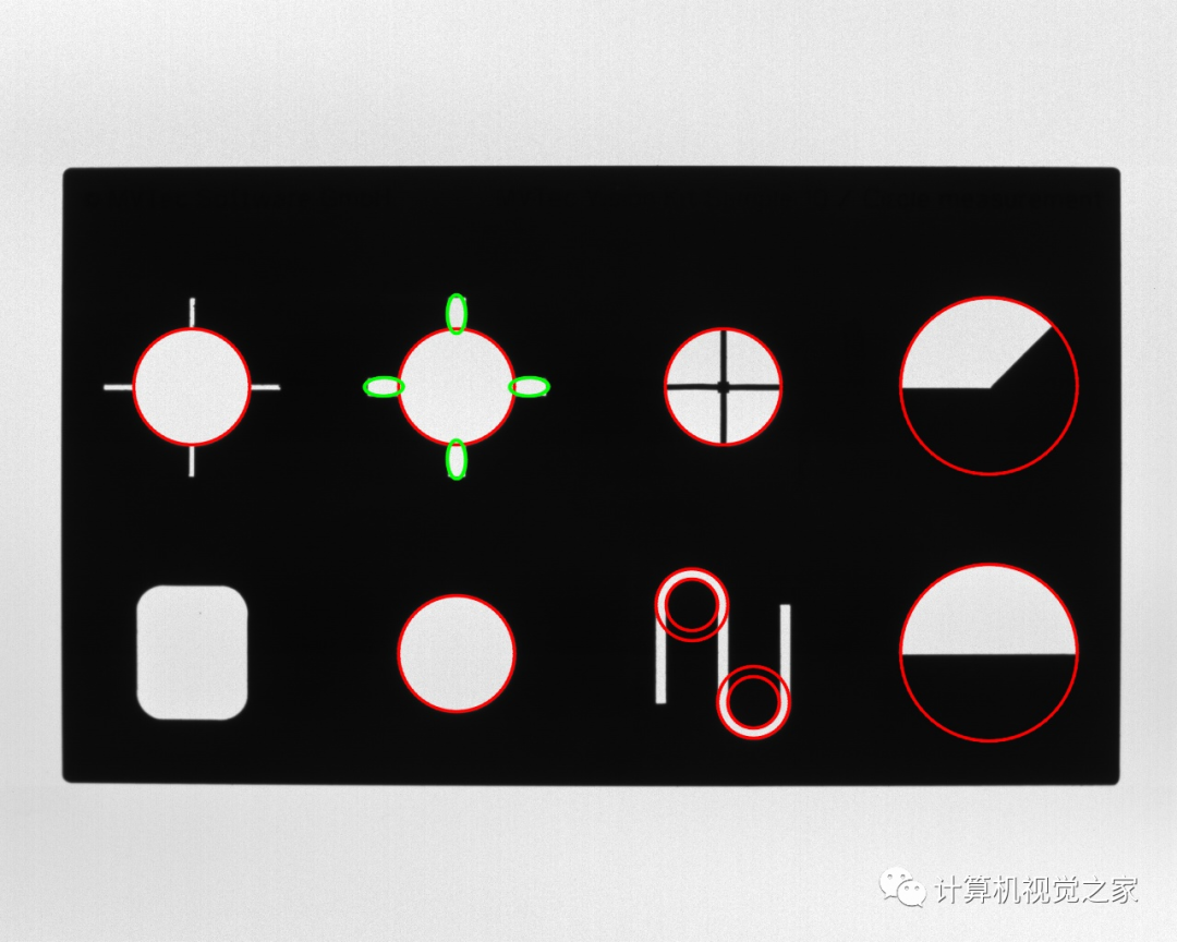
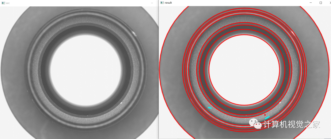
예시 1: edge_drawing.py 1.png
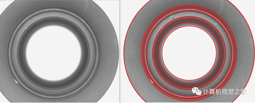
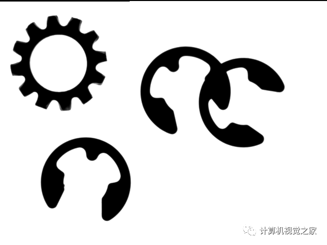
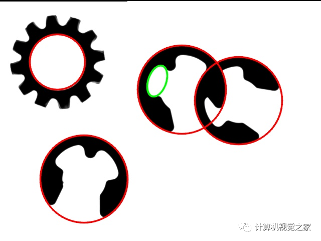
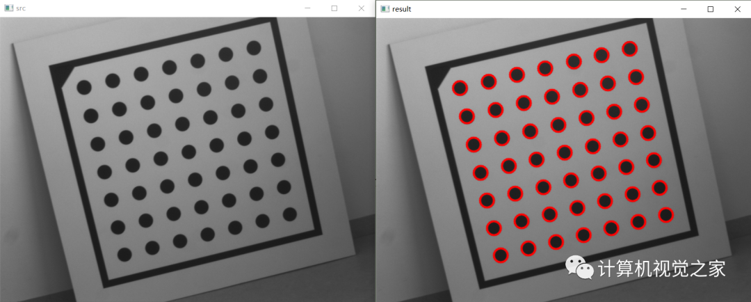
예시 2: edge_drawing.py 2.png
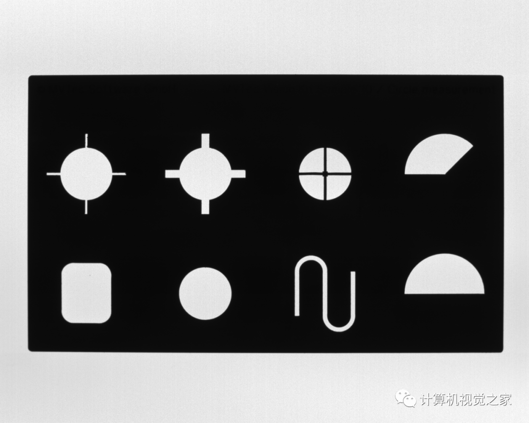
예 3: edge_drawing.py 3.png

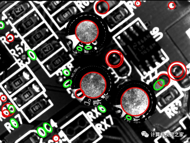
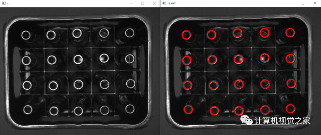
위 그림에서 녹색은 찾은 타원을 나타내고 빨간색은 찾은 원을 나타냅니다. 물론 EdgeDrawing은 가장자리 정보를 얻고 직선을 찾을 수도 있습니다. 그 효과는 다음과 같습니다.
[2] C++ 데모:
//公众号--计算机视觉之家#include <iostream>#include <opencv2/opencv.hpp>#include <opencv2/ximgproc/edge_drawing.hpp>using namespace std;using namespace cv;using namespace ximgproc;int main(){Mat src = imread("./imgs/11.bmp");if (src.empty()){cout << "src image is empty, check again!" << endl;return -1;}//resize(src, src, Size(), 0.2, 0.2);imshow("src", src);Mat gray;cvtColor(src, gray, COLOR_BGR2GRAY);double start = static_cast<double>(getTickCount()); //计时开始Ptr<EdgeDrawing> ed = createEdgeDrawing();ed->params.EdgeDetectionOperator = EdgeDrawing::PREWITT;ed->params.MinPathLength = 50; // try changing this value between 5 to 1000ed->params.PFmode = false; //defaut value try to swich it to trueed->params.MinLineLength = 10; // try changing this value between 5 to 100ed->params.NFAValidation = false; // defaut value try to swich it to falseed->params.GradientThresholdValue = 20;
예 1:
예 2:
예 3:

간단한 요약
일반적으로 EdgeDrawing에서 제공하는 원과 직선을 찾는 방법은 사용하기 쉽고 효과가 좋습니다.간단한 경우에는 기본 매개 변수를 사용할 수 있습니다. 매개변수 조정은 설명서를 참조하여 직접 해보실 수 있으며, 일반적으로 사용되는 몇 가지를 간략하게 설명합니다.
Ptr<EdgeDrawing> ed = createEdgeDrawing();ed->params.EdgeDetectionOperator = EdgeDrawing::LSD;ed->params.MinPathLength = 50; // try changing this value between 5 to 1000ed->params.PFmode = false; //defaut value try to swich it to trueed->params.MinLineLength = 10; // try changing this value between 5 to 100ed->params.NFAValidation = true; // defaut value try to swich it to falseed->params.GradientThresholdValue = 20;
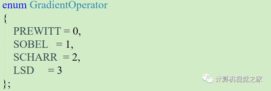
[1] 알고리즘에서 사용하는 기울기 연산자는 4가지 중에서 선택할 수 있으며 기본은 PREWITT이며, 다양한 기울기 연산자를 설정하여 효과를 시험해 볼 수 있습니다.
[2] GradientThresholdValue, 값이 작을수록 대비가 낮은 원을 더 많이 찾을 수 있습니다. 예를 들어 다음은 기울기 임계값이 각각 100과 50인 효과입니다.

【3】NFAV 유효성 검사: 기본값은 참입니다. 선 및 타원 유효성 검사에 NFA(오경보 수) 알고리즘을 사용할지 여부를 나타냅니다. false로 설정하면 더 많은 원이나 선을 찾을 수 있습니다.
【4】MinPathLength: 에지 세그먼트를 생성하기 위한 최소 연결 픽셀 길이 처리. 그래디언트 이미지에서 가장자리 세그먼트를 만들기 위해 처리되는 연결된 픽셀의 최소 길이입니다. GradientThresholdValue보다 높은 값을 가진 픽셀이 처리되며 기본값은 10입니다. 예를 들어, 다음은 기울기 임계값이 각각 50과 10인 효과입니다(값이 작을수록 더 작은 원이 발견됨).