1.交换机的启动序列
1)首先,交换机加载在ROM中的POST。POST检查CPU的子系统。
2)其次,交换机加载启动加载软件。启动加载到ROM中
3)加载器执行CPU的初始化,它初始化CPU寄存器,它控制物理内存的映射
4)启动加载器初始化flash文件系统
5)最终,启动加载器加载IOS
注释:
The IOS operating system then initializes the interfaces using the Cisco IOS commands found in the configuration file, startup-config, which is stored in NVRAM.
In the figure, the BOOT environment variable is set using the boot system global configuration mode command. Notice that the IOS is located in a distinct folder and the folder path is specified. Use the show bootvarcommand (show boot in older IOS versions) to see what the current IOS boot file is set to.
2.从系统文件中恢复
Step 1. Connect a PC by console cable to the switch console port. Configure terminal emulation software to connect to the switch.
Step 2. Unplug the switch power cord.
Step 3. Reconnect the power cord to the switch and, within 15 seconds, press and hold down the Mode button while the System LED is still flashing green.
Step 4. Continue pressing the Mode button until the System LED turns briefly amber and then solid green; then release the Mode button.
Step 5. The boot loader switch: prompt appears in the terminal emulation software on the PC.
3.交换机中的LED
http://cisco.sdut.edu.cn/old/course/RouteSwitch_en/#2.1.1.3
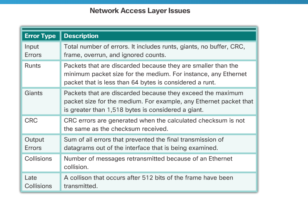
4.show interface brief
5.配置ssh
http://cisco.sdut.edu.cn/old/course/RouteSwitch_en/#2.2.1.2
6.DHCP snooping的配置
The IOS operating system then initializes the interfaces using the Cisco IOS commands found in the configuration file, startup-config, which is stored in NVRAM.
In the figure, the BOOT environment variable is set using the boot system global configuration mode command. Notice that the IOS is located in a distinct folder and the folder path is specified. Use the show bootvarcommand (show boot in older IOS versions) to see what the current IOS boot file is set to.
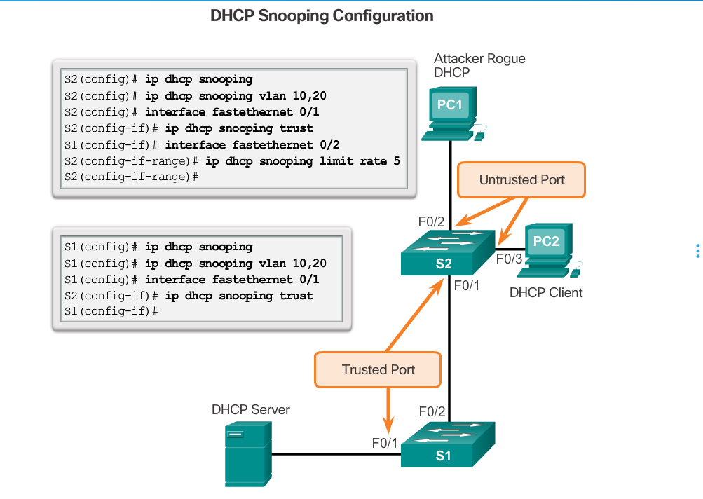
These steps illustrate how to configure DHCP snooping on a Catalyst 2960 switch:
Step 1. Enable DHCP snooping using the ip dhcp snooping global configuration mode command.
Step 2. Enable DHCP snooping for specific VLANs using the ip dhcp snooping vlan number command.
Step 3. Define ports as trusted at the interface level by defining the trusted ports using the ip dhcp snooping trust command.
Step 4. (Optional) Limit the rate at which an attacker can continually send bogus DHCP requests through untrusted ports to the DHCP server using the ip dhcp snooping limit rate rate command.
7.交换机的三种模式

8.本征vlan和管理vlan
本征VLAN(Native Vlan)分配给 802.1Q中继端口。802.1Q中继端口支持来自多个VLAN的流量(有标记流量),也支持来自VLAN以外的流量(无标记流量)。802.1Q中继端口会将无标记流量发送到本征VLAN。如果交换机端口配置了本征VLAN,则连接到该端口的计算机将产生无标记流量。本征VLAN在IEEE 802.1Q规范中说明,其作用是向下兼容传统LAN方案中的无标记流量。对我们来说,本征 VLAN 的目的是充当中继链路两端的公共标识。最佳做法是使用VLAN 1以外的VLAN作为本征VLAN。管理vlan用于远程管理
9.vlan中打tag

10.关于vlan

11.DTP协商

12.
PVLAN Edge
Some applications require that no traffic be forwarded at Layer 2 between ports on the same switch so that one neighbor does not see the traffic generated by another neighbor. In such an environment, the use of the Private VLAN (PVLAN) Edge feature, also known as protected ports, ensures that there is no exchange of unicast, broadcast, or multicast traffic between these ports on the switch (Figure 1)
The PVLAN Edge feature has the following characteristics:
- A protected port does not forward any traffic (unicast, multicast, or broadcast) to any other port that is also a protected port, except for control traffic. Data traffic cannot be forwarded between protected ports at Layer 2.
- Forwarding behavior between a protected port and a nonprotected port proceeds as usual.
- Protected ports must be manually configured.
To configure the PVLAN Edge feature, enter the switchport protectedcommand in interface configuration mode (Figure 2). To disable protected port, use the no switchport protected interface configuration mode command. To verify the configuration of the PVLAN Edge feature, use theshow interfaces interface-id switchport privileged EXEC mode command.
Use the Syntax Checker in Figure 3 to configure the PVLAN Edge feature on interface G0/1 and verify the configuration.
13.Filter Show Command Output
Commands that generate multiple screens of output are, by default, paused after 24 lines. At the end of the paused output, the --More-- text displays. Pressing Enter displays the next line and pressing the spacebar displays the next set of lines. Use the terminal length number command to specify the number of lines to be displayed. A value of 0 (zero) prevents the router from pausing between screens of output.
Another very useful feature that improves the user experience in the command-line interface (CLI) is the filtering of show output. Filtering commands can be used to display specific sections of output. To enable the filtering command, enter a pipe (|) character after the show command and then enter a filtering parameter and a filtering expression.
The filtering parameters that can be configured after the pipe include:
- section - Shows entire section that starts with the filtering expression
- include - Includes all output lines that match the filtering expression
- exclude - Excludes all output lines that match the filtering expression
- begin - Shows all the output lines from a certain point, starting with the line that matches the filtering expression
Note: Output filters can be used in combination with any show command.
Figures 1 to 4 provide examples of the various output filters.
Use the Syntax Checker in Figure 5 to filter output.
14.默认的管理距离

15.远端网络的条目标识符
