一 实验工具
eNSP
二 实验拓扑图

三 实验目的
1.LSW1为192.168.10.0/24网段的主路由,192.168.20.0/24网段的备用路由
2.LSW2为192.168.20.0/24网段的主路由,192.168.10.0/24网段的备用路由
3.当断掉其中一个网段的主路由时,VRRP协议备用路由自动启用
四 实验步骤
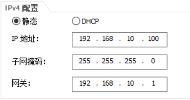
1.1 PC1配置
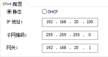
1.2 PC2配置
2. 二层交换机LSW3配置
[SW3]v b 10 20
[SW3]int e0/0/1
[SW3-Ethernet0/0/1]p l a
[SW3-Ethernet0/0/1]p d v 10

[SW3]int e0/0/2
[SW3-Ethernet0/0/2]p l a
[SW3-Ethernet0/0/2]p d v 20

[SW3-Ethernet0/0/2]int g0/0/1
[SW3-GigabitEthernet0/0/1]p l t
[SW3-GigabitEthernet0/0/1]p t a v a

[SW3]int g0/0/2
[SW3-GigabitEthernet0/0/2]p l t
[SW3-GigabitEthernet0/0/2]p t a v a
3.1 三层交换机RSW1配置
划分VLAN
[RSW1]v b 10 20 100
配置接口
[RSW1]int g0/0/2
[RSW1-GigabitEthernet0/0/2]p l t
[RSW1-GigabitEthernet0/0/2]p t a v a
[RSW1-GigabitEthernet0/0/2]int g0/0/1
[RSW1-GigabitEthernet0/0/1]p l a
[RSW1-GigabitEthernet0/0/1]p d v 100
进入逻辑接口配置IP地址
[RSW1-GigabitEthernet0/0/1]int vlanif 10
[RSW1-Vlanif10]ip add 192.168.10.10 24
[RSW1-Vlanif10]int vlanif 20
[RSW1-Vlanif20]ip add 192.168.20.10 24
[RSW1-Vlanif20]int vlanif 100
[RSW1-Vlanif100]ip add 11.0.0.2 30
VRRP协议
[RSW1]int vlanif 10
[RSW1-Vlanif10]vrrp vrid 1 virtual-ip 192.168.10.1		#虚拟路由器IP地址
[RSW1-Vlanif10]vrrp vrid 1 priority 120					#VRRP优先级设置
[RSW1-Vlanif10]vrrp vrid 1 track interface g0/0/1		#监控RSW1的g0/0/1接口
[RSW1-Vlanif10]vrrp vrid 1 track interface g0/0/2		#监控RSW1的g0/0/2接口
VRRP备用路由
[RSW1]int Vlanif 20
[RSW1-Vlanif20]vrrp vrid 2 virtual-ip 192.168.20.1
[RSW1-Vlanif20]vrrp vrid 2 priority 115					#VRRP优先级低于主路由器

默认路由
[RSW1]ip route-static 0.0.0.0 0.0.0.0 11.0.0.1			#边缘路由器配置默认路由
3.2 三层交换机RSW2配置
划分VLAN
[RSW2]v b 10 20 100
配置接口
[RSW2]int g0/0/2
[RSW2-GigabitEthernet0/0/2]p l t
[RSW2-GigabitEthernet0/0/2]p t a v a
[RSW2-GigabitEthernet0/0/2]int g0/0/1
[RSW2-GigabitEthernet0/0/1]p l a
[RSW2-GigabitEthernet0/0/1]p d v 100
[RSW2-GigabitEthernet0/0/2]int vlanif 10
[RSW2-Vlanif10]ip add 192.168.10.20 24
进入逻辑接口配置IP地址
[RSW2-GigabitEthernet0/0/1]int vlanif 10
[RSW2-Vlanif10]ip add 192.168.10.20 24
[RSW2-Vlanif10]int vlanif 20
[RSW2-Vlanif20]ip add 192.168.20.20 24
[RSW2-Vlanif20]int vlanif 100
[RSW2-Vlanif100]ip add 12.0.0.2 30
VRRP备用路由
[RSW2-Vlanif10]vrrp vrid 1 virtual-ip 192.168.10.1
[RSW2-Vlanif10]vrrp vrid 1 priority 115
VRRP主路由
[RSW2-Vlanif10]int vlanif 20
[RSW2-Vlanif20]vrrp vrid 2 virtual-ip 192.168.20.1
[RSW2-Vlanif20]vrrp vrid 2 priority 120
[RSW2-Vlanif20]vrrp vrid 2 track interface GigabitEthernet 0/0/1
[RSW2-Vlanif20]vrrp vrid 2 track interface GigabitEthernet 0/0/2

默认路由
[RSW2]ip route-static 0.0.0.0 0.0.0.0 12.0.0.1
4 路由器R1配置
接口IP地址配置
[R1]int g0/0/0
[R1-GigabitEthernet0/0/0]ip add 11.0.0.1 30
[R1-GigabitEthernet0/0/0]un sh

[R1-GigabitEthernet0/0/0]int g0/0/1
[R1-GigabitEthernet0/0/1]ip add 12.0.0.1 30
[R1-GigabitEthernet0/0/1]un sh

[R1-GigabitEthernet0/0/1]int loo 0
[R1-LoopBack0]ip add 1.1.1.1 24
浮动路由
[R1]ip route-static 192.168.10.0 255.255.255.0 12.0.0.2 preference 70
[R1]ip route-static 192.168.20.0 255.255.255.0 11.0.0.2 preference 70
[R1]ip route-static 192.168.20.0 255.255.255.0 12.0.0.2
[R1]ip route-static 192.168.10.0 255.255.255.0 11.0.0.2
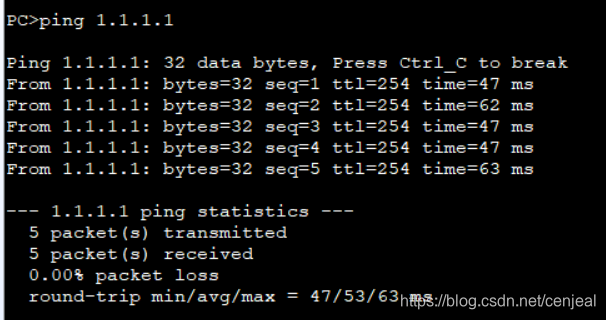
5 测试连通
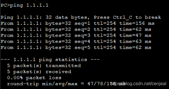
PC1ping loopback 0接口
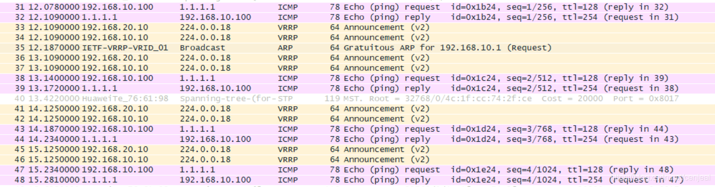
报文数据
PC2 ping loopback 0接口
报文数据
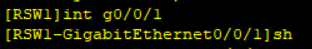
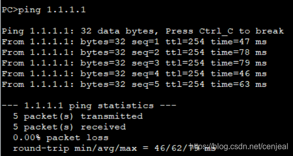
当11.0.0.0/30网段down掉后
依旧可以ping通
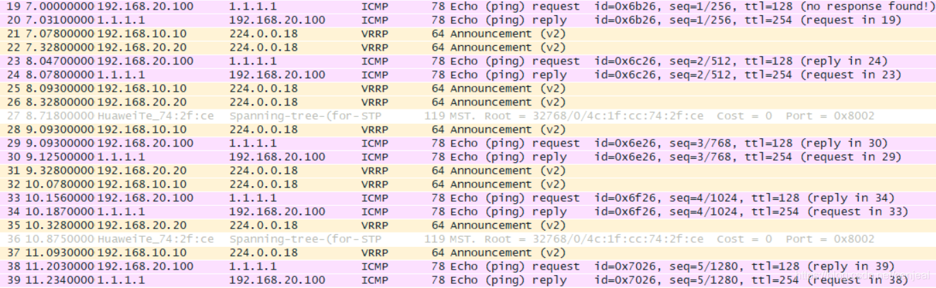
从RSW2的g0/0/2接口抓包发现ICMP报文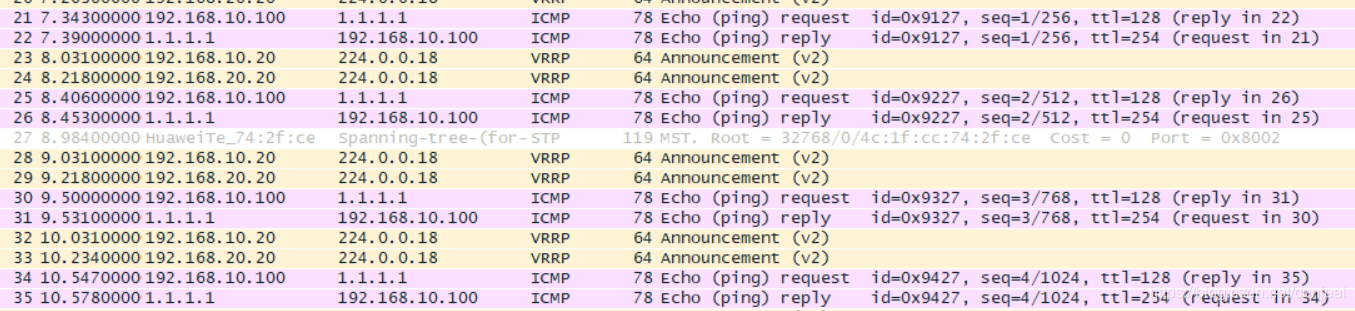
至此,实验结束。