前言
STM32的串口通信是最常用的通信方式,串口通信(Serial Communications)的概念非常简单,串口按位(bit)发送和接收字节。尽管比按字节(byte)的并行通信慢,但是串口可以在使用一根线发送数据的同时用另一根线接收数据。它很简单并且能够实现远距离通信。下面根据stm32f1的中文手册和stm32f1固件库来配置一个串口。
stm32f1的中文手册和stm32f1固件库
链接:https://pan.baidu.com/s/1dMGIH9Cq-UBruGPraDPQvg
提取码:2333
查看原理图
通过STM32F103RET6的原理图知道串口1的管脚为PA9和PA10,下面就需要将这两个管脚配置为串口1。

引脚初始化
和配置GPIO一样,使用引脚前需要使能RCC时钟,查看总线架构可以知道,GPIOA和USART1是在APB2下的。

查看STM32F1的库函数手册初始化函数。
RCC_APB2PeriphClockCmd(RCC_APB2Periph_GPIOA | RCC_APB2Periph_USART1 , ENABLE);
开启RCC时钟后,就可以进行引脚初始化了,查看库函数中的GPIO_Init函数,找到下面的实例,复制修改一下即可。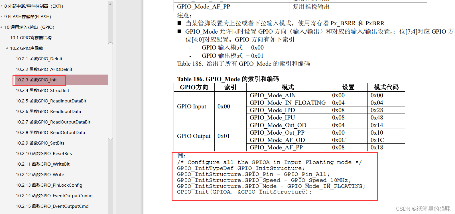
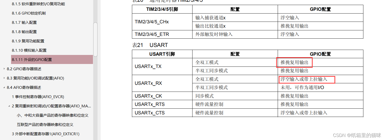
串口的引脚模式要根据STM32F1中文参考手册的8.1.11外设的GPIO配置来配置,将PA9.TX配置为推挽复用输出,PA10.RX配置为上拉输入。
	GPIO_InitTypeDef GPIO_InitStructure;
	 //PA9.TX
	GPIO_InitStructure.GPIO_Pin = GPIO_Pin_9; //PA9
	GPIO_InitStructure.GPIO_Speed = GPIO_Speed_50MHz;
	GPIO_InitStructure.GPIO_Mode = GPIO_Mode_AF_PP; //复用推挽输出
	GPIO_Init(GPIOA, &GPIO_InitStructure);
	//PA10.RX
	GPIO_InitStructure.GPIO_Pin = GPIO_Pin_10; //PA10
	GPIO_InitStructure.GPIO_Speed = GPIO_Speed_50MHz;
	GPIO_InitStructure.GPIO_Mode = GPIO_Mode_IPU; //上拉输入
	GPIO_Init(GPIOA, &GPIO_InitStructure);
串口初始化
查看STM32F1的库函数中文参考手册的USART_Init,根据 USART_InitStruct 中指定的参数初始化外设 USARTx 寄存器,一般只需要配置前六将,后面四想默认配置即可

USART_InitTypeDef USART_InitStructure;
USART_InitStructure.USART_BaudRate = 115200; //设置波特率
USART_InitStructure.USART_WordLength = USART_WordLength_8b; //8 位数据
USART_InitStructure.USART_StopBits = USART_StopBits_1;//在帧结尾传输 1 个停止位
USART_InitStructure.USART_Parity = USART_Parity_No; //奇偶失能,无校验
USART_InitStructure.USART_HardwareFlowControl = USART_HardwareFlowControl_None;// 硬件流控制失能
USART_InitStructure.USART_Mode = USART_Mode_Tx | USART_Mode_Rx;//发送、接收使能
完整配置代码
void Usart1_Init(void)//串口1初始化
{


	//GPIO端口配置
	GPIO_InitTypeDef GPIO_InitStructure;
	RCC_APB2PeriphClockCmd(RCC_APB2Periph_GPIOA | RCC_APB2Periph_USART1 , ENABLE);//使能RCC时钟
	 //PA9.TX
	GPIO_InitStructure.GPIO_Pin = GPIO_Pin_9; //PA9
	GPIO_InitStructure.GPIO_Speed = GPIO_Speed_50MHz;
	GPIO_InitStructure.GPIO_Mode = GPIO_Mode_AF_PP; //复用推挽输出
	GPIO_Init(GPIOA, &GPIO_InitStructure);
	//PA10.RX
	GPIO_InitStructure.GPIO_Pin = GPIO_Pin_10; //PA10
	GPIO_InitStructure.GPIO_Speed = GPIO_Speed_50MHz;
	GPIO_InitStructure.GPIO_Mode = GPIO_Mode_IPU; //上拉输入
	GPIO_Init(GPIOA, &GPIO_InitStructure);

	//USART 初始化设置
	USART_InitTypeDef USART_InitStructure;

	USART_InitStructure.USART_BaudRate = 115200; //设置波特率
	USART_InitStructure.USART_WordLength = USART_WordLength_8b; //8 位数据
	USART_InitStructure.USART_StopBits = USART_StopBits_1;//在帧结尾传输 1 个停止位
	USART_InitStructure.USART_Parity = USART_Parity_No; //奇偶失能,无校验
	USART_InitStructure.USART_HardwareFlowControl = USART_HardwareFlowControl_None;// 硬件流控制失能
	USART_InitStructure.USART_Mode = USART_Mode_Tx | USART_Mode_Rx;//发送、接收使能

	USART_Init(USART1, &USART_InitStructure);//初始化串口1
	USART_Cmd(USART1, ENABLE);               //使能串口1

}
发送单个数据
void Usart1_sentbyte(char data)
{


	while(!(USART_GetFlagStatus(USART1, USART_FLAG_TXE)==SET));
	USART_SendData(USART1,data);

}
发送字符串
void Usart1_sentstring(char *data)
{


	while(*data)
	Usart1_sentbyte(*data++);

}
接收字符
char Usart1_Receivebyte(void)
{


	while(!(USART_GetFlagStatus(USART1, USART_FLAG_RXNE)==SET));
	return USART_ReceiveData(USART1);
}