一般而言,防火墙部署于公司网络的出口位置,以便对进出公司的所有访问流量进行限制。然而,如果防火墙部署在公司网络出口位置,一旦防火墙发生故障,就会影响到整个网络业务。因此,为了提升防火墙的可靠性,可以类似路由交换设备中的VRRP技术一样,配置防火墙双机热备技术。
在防火墙双击热备架构中,当一台防火墙出现故障时,业务流量能平稳地切换到另一台防火墙上,保证流量业务不中断,使得对内外网用户透明,感知不到防火墙的故障。
二、本拓扑设计图涉及多种协议配置,其中包括:
1、Eth-Trunk链路捆绑
2、vlan 底层配置
3、MSTP多生成树
4、VRRP网关配置
5、DHCP中继
6、dhcp snooping配置
7、访问FTP控制列表
8、防火墙基础配置及双机热备
9、ISP1、ISP2及连接FW1、FW2核心交换机接口配置
10、OSPF配置
11、wlan配置
12、部分功能测试情况
三、设计要求:
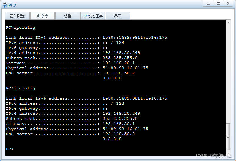
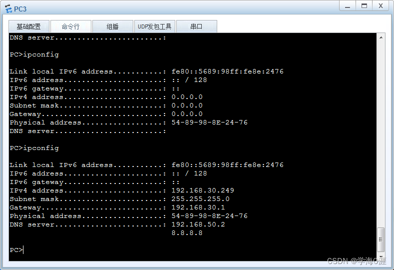
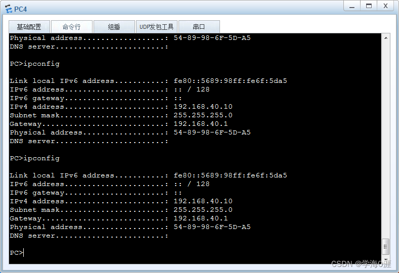
1、内网终端能从DHCP服务器上自动获取IP地址
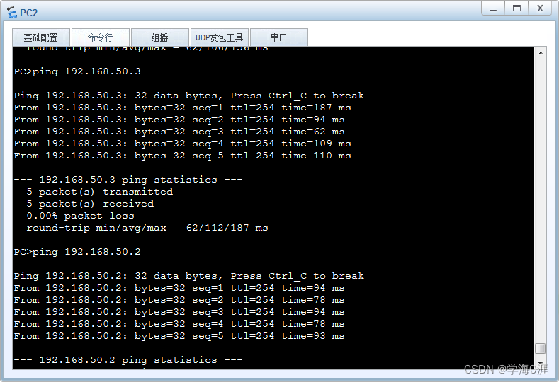
2、内网部门之间不能互访,且都能访问外网,会客厅不能访问内网FTP服务器
3、内部网络访问外网时优先走ISP1,当ISP1链路故障即切换到ISP2上
4、双机热备FW1为主要链路。FW2为备份链路,当FW1故障时,线路切换至FW2
5、核心交换机使用VRRP做负载分担及冗余设计,但其中一台设备故障能,能正常切换到另一台。
6、AC旁挂在SW2上,wlan配置会客厅无需密码即可登入,其他部门需要密码登入网络
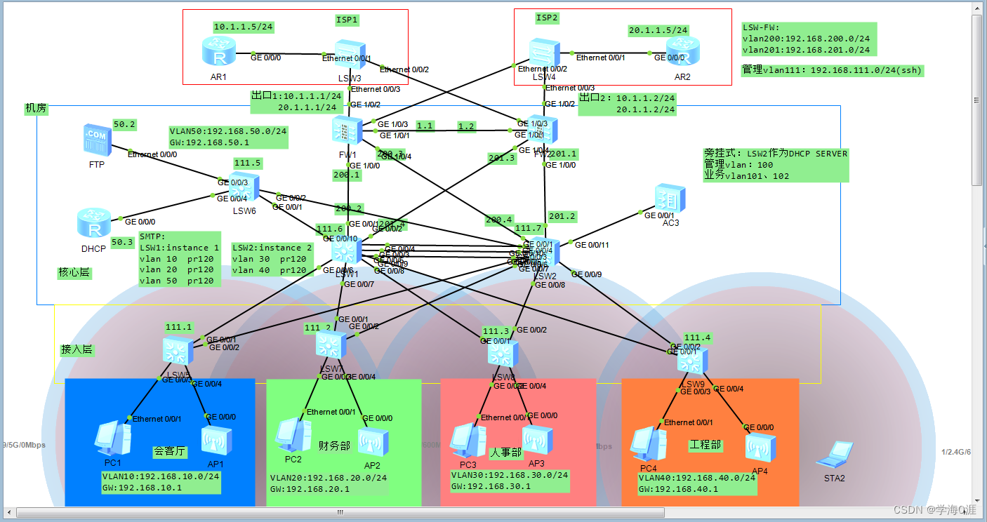
拓扑图如下:
四:配置过程及相应命令:
1、核心交换机之间eth-trunk链路配置:
<Huawei>sy
Enter system view, return user view with Ctrl+Z.
[Huawei]sys LW1
[LW1]
[LW1]int eth-trunk 1  进入聚合端口
[LW1-Eth-Trunk1]mode lacp-static  定义为LACP模式
[LW1-Eth-Trunk1]po link-type tr
[LW1-Eth-Trunk1]po trunk allow-pass vlan all  允许所有流量通行
[LW1-Eth-Trunk1]trunkport GigabitEthernet 0/0/3 to 0/0/5  添加聚合端口

<sw>sy
Enter system view, return user view with Ctrl+Z.
[sw]sys LW2
[LW2]int eth-trunk 1
[LW2-Eth-Trunk1]mode lacp-static
[LW2-Eth-Trunk1]po link-type tr
[LW2-Eth-Trunk1]po tr allow-pass vlan all
[LW2-Eth-Trunk1]trunkport GigabitEthernet 0/0/3 to 0/0/5
2、vlan二层配置:
LW1:
[LW1]vlan batch 10 20 30 40 50 200 201 111
Info: This operation may take a few seconds. Please wait for a moment...done.
[LW1]int g0/0/6
[LW1-GigabitEthernet0/0/6]po link-type tr
[LW1-GigabitEthernet0/0/6]po tr allow-pass vlan 10 111
[LW1-GigabitEthernet0/0/6]int g0/0/7
[LW1-GigabitEthernet0/0/7]po link-type tr
[LW1-GigabitEthernet0/0/7]po tr allow-pass vlan 20 111
[LW1-GigabitEthernet0/0/7]int g0/0/8
[LW1-GigabitEthernet0/0/8]po link-type tr
[LW1-GigabitEthernet0/0/8]po tr allow-pass vlan 30 111
[LW1-GigabitEthernet0/0/8]int g0/0/9
[LW1-GigabitEthernet0/0/9]po link-type tr
[LW1-GigabitEthernet0/0/9]po tr allow-pass vlan 40 111
[LW1-GigabitEthernet0/0/9]int g0/0/10
[LW1-GigabitEthernet0/0/10]po link-type tr
[LW1-GigabitEthernet0/0/10]po tr allow-pass vlan 50 111
[LW1-GigabitEthernet0/0/10]int g0/0/1
[LW1-GigabitEthernet0/0/1]po link-ty ac
[LW1-GigabitEthernet0/0/1]po default vlan 200
[LW1-GigabitEthernet0/0/1]int g0/0/2
[LW1-GigabitEthernet0/0/2]po link-type ac
[LW1-GigabitEthernet0/0/2]po default vlan 201

LW2:
[LW2]vlan batch 10 20 30 40 50 100 101
Info: This operation may take a few seconds. Please wait for a moment...done.
[LW2]vlan batch 111 102 200 201
Info: This operation may take a few seconds. Please wait for a moment...done.
[LW2]int g0/0/6
[LW2-GigabitEthernet0/0/6]po link-type tr
[LW2-GigabitEthernet0/0/6]po tr allow-pass vlan 10 111 100 101 102
[LW2-GigabitEthernet0/0/6]int g0/0/7
[LW2-GigabitEthernet0/0/7]po link-type tr
[LW2-GigabitEthernet0/0/7]po tr allow-pass vlan 20 100 101 102 111
[LW2-GigabitEthernet0/0/7]int g0/0/8
[LW2-GigabitEthernet0/0/8]po link-type tr
[LW2-GigabitEthernet0/0/8]po tr allow-pass vlan 30 100 101 102 111
[LW2-GigabitEthernet0/0/8]int g0/0/9
[LW2-GigabitEthernet0/0/9]po link-type tr
[LW2-GigabitEthernet0/0/9]po tr allow-pass vlan 40 100 101 102 111
[LW2-GigabitEthernet0/0/9]int g0/0/10
[LW2-GigabitEthernet0/0/10]po link-type tr
[LW2-GigabitEthernet0/0/10]po tr allow-pass vlan 50 111
[LW2-GigabitEthernet0/0/10]int g0/0/1
[LW2-GigabitEthernet0/0/1]po link-type ac
[LW2-GigabitEthernet0/0/1]po de vlan 201
[LW2-GigabitEthernet0/0/1]int g0/0/2
[LW2-GigabitEthernet0/0/2]po link-ty ac
[LW2-GigabitEthernet0/0/2]po de vlan 200

JR1:
<Huawei>sy
Enter system view, return user view with Ctrl+Z.
[Huawei]sys JR1
[JR1]vlan batch 10 20 30 40 50 111 100 101 102
Info: This operation may take a few seconds. Please wait for a moment...done.
[JR1]int g0/0/1
[JR1-GigabitEthernet0/0/1]po link-ty tr
[JR1-GigabitEthernet0/0/1]po tr allow-pass vlan 10 111
[JR1-GigabitEthernet0/0/1]int g0/0/2
[JR1-GigabitEthernet0/0/2]po link-type tr
[JR1-GigabitEthernet0/0/2]po tr allow-pass vlan 10 111 100 101 102
[JR1-GigabitEthernet0/0/2]int g0/0/3
[JR1-GigabitEthernet0/0/3]po link-ty ac
[JR1-GigabitEthernet0/0/3]po de vlan 10
[JR1-GigabitEthernet0/0/3]int g0/0/4
[JR1-GigabitEthernet0/0/4]po link-ty tr
[JR1-GigabitEthernet0/0/4]po tr allow-pass vlan 100 101 102
[JR1-GigabitEthernet0/0/4]po tr pvid vlan 100

JR2:
<Huawei>sy
Enter system view, return user view with Ctrl+Z.
[Huawei]sys JR2
[JR2]vlan batch 10 20 30 40 50 111 100 101 102
Info: This operation may take a few seconds. Please wait for a moment...done.
[JR2]int g0/0/1
[JR2-GigabitEthernet0/0/1]po link-ty tr
[JR2-GigabitEthernet0/0/1]po tr allow-pass vlan 20 111
[JR2-GigabitEthernet0/0/1]int g0/0/2
[JR2-GigabitEthernet0/0/2]po link-ty tr
[JR2-GigabitEthernet0/0/2]po tr allow-pass vlan 20 111 100 101 102
[JR2-GigabitEthernet0/0/2]int g0/0/3
[JR2-GigabitEthernet0/0/3]po link-ty ac
[JR2-GigabitEthernet0/0/3]po de vlan 20
[JR2-GigabitEthernet0/0/3]int g0/0/4
[JR2-GigabitEthernet0/0/4]po link-ty tr
[JR2-GigabitEthernet0/0/4]po tr allow-pass vlan 100 101 102
[JR2-GigabitEthernet0/0/4]po tr pvid vlan 100

JR3:
<Huawei>sy
Enter system view, return user view with Ctrl+Z.
[Huawei]sys JR3
[JR3]vlan batch 10 20 30 40 50 111 100 101 102
Info: This operation may take a few seconds. Please wait for a moment...done.
[JR3]int g0/0/1
[JR3-GigabitEthernet0/0/1]po link-ty tr
[JR3-GigabitEthernet0/0/1]po tr allow-pass vlan 30 111
[JR3-GigabitEthernet0/0/1]int g0/0/2
[JR3-GigabitEthernet0/0/2]po link-ty tr
[JR3-GigabitEthernet0/0/2]po tr allow-pass vlan 30 111 100 101 102
[JR3-GigabitEthernet0/0/2]
[JR3-GigabitEthernet0/0/2]int g0/0/3
[JR3-GigabitEthernet0/0/3]po link-ty ac
[JR3-GigabitEthernet0/0/3]po de vlan 30
[JR3-GigabitEthernet0/0/3]int g0/0/4
[JR3-GigabitEthernet0/0/4]po link-ty tr
[JR3-GigabitEthernet0/0/4]po tr allow-pass vlan 100 101 102
[JR3-GigabitEthernet0/0/4]po tr pvid vlan 100

JR4:
<Huawei>sy
Enter system view, return user view with Ctrl+Z.
[Huawei]sys JR4
[JR4]vlan batch 10 20 30 40 50 111 100 101 102
Info: This operation may take a few seconds. Please wait for a moment...done.
[JR4]int g0/0/1
[JR4-GigabitEthernet0/0/1]po link-ty tr
[JR4-GigabitEthernet0/0/1]po tr allow-pass vlan 40 111
[JR4-GigabitEthernet0/0/1]int g0/0/2
[JR4-GigabitEthernet0/0/2]po link-ty tr
[JR4-GigabitEthernet0/0/2]po tr allow-pass vlan 40 111 100 101 102
[JR4-GigabitEthernet0/0/2]int g0/0/3
[JR4-GigabitEthernet0/0/3]po link-ty ac
[JR4-GigabitEthernet0/0/3]po de vlan 40
[JR4-GigabitEthernet0/0/3]int g0/0/4
[JR4-GigabitEthernet0/0/4]po link-ty tr
[JR4-GigabitEthernet0/0/4]po tr allow-pass vlan 100 101 102
[JR4-GigabitEthernet0/0/4]po tr pvid vlan 100

JR5:
<Huawei>sy
Enter system view, return user view with Ctrl+Z.
[Huawei]sys JR5
[JR5]vlan batch 10 20 30 40 50 111
Info: This operation may take a few seconds. Please wait for a moment...done.
[JR5]int g0/0/1
[JR5-GigabitEthernet0/0/1]po link-ty tr
[JR5-GigabitEthernet0/0/1]po tr allow-pass vlan 50 111
[JR5-GigabitEthernet0/0/1]int g0/0/2
[JR5-GigabitEthernet0/0/2]po link-ty tr
[JR5-GigabitEthernet0/0/2]po tr allow-pass vlan 50 111
[JR5-GigabitEthernet0/0/2]int g0/0/3
[JR5-GigabitEthernet0/0/3]po link-ty ac
[JR5-GigabitEthernet0/0/3]po de vlan 50
[JR5-GigabitEthernet0/0/3]int g0/0/4
[JR5-GigabitEthernet0/0/4]po link-ty ac
[JR5-GigabitEthernet0/0/4]po de vlan 50
3、MSTP配置:
LW1:
[LW1]stp en
[LW1]stp mode mstp 定义为MSTP
[LW1]stp region-configuration  进入stp视图
[LW1-mst-region]region-name stp  命名
[LW1-mst-region]revision-level 1
[LW1-mst-region]instance 1 vlan 10 20 50  配置生成树实例和VLAN的映射关系

[LW1-mst-region]instance 2 vlan 30 40
[LW1-mst-region]active region-configuration  激活MST域的配置(这个命令必须开启)
Info: This operation may take a few seconds. Please wait for a moment...done.
[LW1-mst-region]
[LW1-mst-region]stp instance 1 root primary 配置当前设备为生成树实例1的根桥设备
[LW1]stp instance 2 root secondary  配置当前设备为生成树实例2的备份根桥设备


LW2:
[LW2]stp en
[LW2]stp mode mstp
[LW2]stp region-configuration
[LW2-mst-region]region-name stp
[LW2-mst-region]revision-level 1
[LW2-mst-region]instance 1 vlan 10 20 50
[LW2-mst-region]instance 2 vlan 30 40
[LW2-mst-region]active region-configuration
Info: This operation may take a few seconds. Please wait for a moment...done.
[LW2-mst-region]
[LW2-mst-region]stp instance 1 root secondary
[LW2]stp instance 2 root primary

JR1:
[JR1]stp en
[JR1]stp mode mstp
[JR1]stp region-configuration
[JR1-mst-region]region-name stp
[JR1-mst-region]revision-level 1
[JR1-mst-region]instance 1 vlan 10 20 50
[JR1-mst-region]instance 2 vlan 30 40
[JR1-mst-region]active region-configuration

JR2:
[JR2]stp en
[JR2]stp mode mstp
[JR2]stp region-configuration
[JR2-mst-region]region-name stp
[JR2-mst-region]revision-level 1
[JR2-mst-region]instance 1 vlan 10 20 50
[JR2-mst-region]instance 2 vlan 30 40
[JR2-mst-region]active region-configuration

JR3:
[JR3]stp en
[JR3]stp mode mstp
[JR3]stp region-configuration
[JR3-mst-region]region-name stp
[JR3-mst-region]revision-level 1
[JR3-mst-region]instance 1 vlan 10 20 50
[JR3-mst-region]instance 2 vlan 30 40
[JR3-mst-region]active region-configuration

JR4:
[JR4]stp en
[JR4]stp mode mstp
[JR4]stp region-configuration
[JR4-mst-region]region-name stp
[JR4-mst-region]revision-level 1
[JR4-mst-region]instance 1 vlan 10 20 50
[JR4-mst-region]instance 2 vlan 30 40
[JR4-mst-region]active region-configuration

JR5:
[JR5]stp en
[JR5]stp mode mstp
[JR5]stp region-configuration
[JR5-mst-region]region-name stp
[JR5-mst-region]revision-level 1
[JR5-mst-region]instance 1 vlan 10 20 50
[JR5-mst-region]instance 2 vlan 30 40
[JR5-mst-region]active region-configuration
4、 VRRP网关冗余配置:
LW1:
[LW1]int vlan 10 进入vlanif视图
[LW1-Vlanif10]ip add 192.168.10.254 24  配置vlanif10虚拟地址
[LW1-Vlanif10]vrrp vrid 10 virtual-ip 192.168.10.1  配置vrid 1 中的虚拟网关地址
[LW1-Vlanif10]vrrp vrid 10 priority  120  配置该接口在vrid 1 中的优先级,缺省为100(数值越大越优先)
[LW1-Vlanif10]int vlan 20
[LW1-Vlanif20]ip add 192.168.20.254 24
[LW1-Vlanif20]vrrp vrid 20 virtual-ip 192.168.20.1
[LW1-Vlanif20]vrrp vrid 20 priority  120
[LW1-Vlanif20]int vlan 30
[LW1-Vlanif30]ip add 192.168.30.254 24
[LW1-Vlanif30]vrrp vrid 30 virtual-ip 192.168.30.1
[LW1-Vlanif30]int vlan 40
[LW1-Vlanif40]ip add 192.168.40.254 24
[LW1-Vlanif40]vrrp vrid 40 virtual-ip 192.168.40.1
[LW1-Vlanif40]int vlan 50
[LW1-Vlanif50]ip add 192.168.50.254 24
[LW1-Vlanif50]vrrp vrid 50 virtual-ip 192.168.50.1
[LW1-Vlanif50]vrrp vrid 50 priority  120

LW2:
[LW2]int vlan 10
[LW2-Vlanif10]ip add 192.168.10.253 24
[LW2-Vlanif10]vrrp vrid 10 virtual-ip 192.168.10.1
[LW2-Vlanif10]int vlan 20
[LW2-Vlanif20]ip add 192.168.20.253 24
[LW2-Vlanif20]vrrp vrid 20 virtual-ip 192.168.20.1
[LW2-Vlanif20]int vlan 30
[LW2-Vlanif30]ip add 192.168.30.253 24
[LW2-Vlanif30]vrrp vrid 30 virtual-ip 192.168.30.1
[LW2-Vlanif30]vrrp vrid 30 priority  120
[LW2-Vlanif30]int vlan 40
[LW2-Vlanif40]ip add 192.168.40.253 24
[LW2-Vlanif40]vrrp vrid 40 virtual-ip 192.168.40.1
[LW2-Vlanif40]vrrp vrid 40 priority  120
[LW2-Vlanif40]int vlan 50
[LW2-Vlanif50]ip add 192.168.50.253 24
[LW2-Vlanif50]vrrp vrid 50 virtual-ip 192.168.50.1
5、DHCP服务器配置及中继配置:
DHCP:
<Huawei>sy
Enter system view, return user view with Ctrl+Z.
[Huawei]
[Huawei]sys DHCP
[DHCP]
[DHCP]dhcp en  开启DHCP功能
Info: The operation may take a few seconds. Please wait for a moment.done.
[DHCP]
[DHCP]ip pool vlan10  创建地址池
Info: It's successful to create an IP address pool.
[DHCP-ip-pool-vlan10]network 192.168.10.0 mask 24  配置网络段及掩码
[DHCP-ip-pool-vlan10]gateway-list 192.168.10.1  配置网关
[DHCP-ip-pool-vlan10]dns-list 8.8.8.8  配置DNS服务器
[DHCP-ip-pool-vlan10]excluded-ip-address 192.168.10.250 192.168.10.254  排除该地址不能获取
[DHCP-ip-pool-vlan10]ip pool vlan20
Info: It's successful to create an IP address pool.
[DHCP-ip-pool-vlan20]network 192.168.20.0 mask 24
[DHCP-ip-pool-vlan20]dns-list  8.8.8.8
[DHCP-ip-pool-vlan20]excluded-ip-address 192.168.20.250 192.168.20.254
[DHCP-ip-pool-vlan20]ip pool vlan30
Info: It's successful to create an IP address pool.
[DHCP-ip-pool-vlan30]network 192.168.30.0 mask 24
[DHCP-ip-pool-vlan30]gateway-list 192.168.30.1
[DHCP-ip-pool-vlan30]dns-list  8.8.8.8
[DHCP-ip-pool-vlan30]excluded-ip-address 192.168.30.250 192.168.30.254
[DHCP-ip-pool-vlan30]ip pool vlan40
Info: It's successful to create an IP address pool.
[DHCP-ip-pool-vlan40]network 192.168.40.0 mask 24
[DHCP-ip-pool-vlan40]gateway-list 192.168.40.1
[DHCP-ip-pool-vlan40]dns-list  8.8.8.8
[DHCP-ip-pool-vlan40]excluded-ip-address 192.168.40.250 192.168.40.254
[DHCP-ip-pool-vlan40]int g0/0/0
[DHCP-GigabitEthernet0/0/0]ip add 192.168.50.3 24
[DHCP-GigabitEthernet0/0/0]dhcp select global  在全局中获取地址
[DHCP-GigabitEthernet0/0/0]ip route-s 0.0.0.0 0 192.168.50.1  配置静态路由

LW1:
[LW1]dhcp en
Info: The operation may take a few seconds. Please wait for a moment.done.
[LW1]int vlan 10
[LW1-Vlanif10]dhcp select relay  配置该vlanif为中继
[LW1-Vlanif10]dhcp relay server-ip 192.168.50.3  自动获取的地址在该接口地址处获取
[LW1-Vlanif10]int vlan 20
[LW1-Vlanif20]dhcp select relay
[LW1-Vlanif20]dhcp relay server-ip 192.168.50.3
[LW1-Vlanif20]int vlan 30
[LW1-Vlanif30]dhcp select relay
[LW1-Vlanif30]dhcp relay server-ip 192.168.50.3
[LW1-Vlanif30]int v 40
[LW1-Vlanif40]dhcp select relay
[LW1-Vlanif40]dhcp relay server-ip 192.168.50.3

LW2:
[LW2]dhcp en
Info: The operation may take a few seconds. Please wait for a moment.done.
[LW2]int vlan 10
[LW2-Vlanif10]dhcp select relay
[LW2-Vlanif10]dhcp relay server-ip 192.168.50.3
[LW2-Vlanif10]int vlan 20
[LW2-Vlanif20]dhcp select relay
[LW2-Vlanif20]dhcp relay server-ip 192.168.50.3
[LW2-Vlanif20]int vlan 30
[LW2-Vlanif30]dhcp select relay
[LW2-Vlanif30]dhcp relay server-ip 192.168.50.3
[LW2-Vlanif30]int v 40
[LW2-Vlanif40]dhcp select relay
[LW2-Vlanif40]dhcp relay server-ip 192.168.50.3
6、DHCP Snooping配置:
JR1:
[JR1]dhcp en 开启DHCP
Info: The operation may take a few seconds. Please wait for a moment.done.
[JR1]dhcp snooping en  开启DHCP Snooping 功能
[JR1]vlan 10
[JR1-vlan10]dhcp snooping en  在vlan10 snooping功能开启
[JR1-vlan10]int g0/0/1
[JR1-GigabitEthernet0/0/1]dhcp snooping trusted  配置snooping信任接口
[JR1-GigabitEthernet0/0/1]int g0/0/2
[JR1-GigabitEthernet0/0/2]dhcp snooping trusted

JR2:
[JR2]dhcp en
Info: The operation may take a few seconds. Please wait for a moment.done.
[JR2]dhcp snooping en
[JR2]vlan 20
[JR2-vlan20]dhcp snooping en
[JR2-vlan20]int g0/0/1
[JR2-GigabitEthernet0/0/1]dhcp snooping trusted
[JR2-GigabitEthernet0/0/1]int g0/0/2
[JR2-GigabitEthernet0/0/2]dhcp snooping trusted

JR3:
[JR3]dhcp en
Info: The operation may take a few seconds. Please wait for a moment.done.
[JR3]dhcp snooping en
[JR3]vlan 30
[JR3-vlan30]dhcp snooping en
[JR3-vlan30]int g0/0/1
[JR3-GigabitEthernet0/0/1]dhcp snooping trusted
[JR3-GigabitEthernet0/0/1]int g0/0/2
[JR3-GigabitEthernet0/0/2]dhcp snooping trusted

JR4:
[JR4]dhcp en
Info: The operation may take a few seconds. Please wait for a moment.done.
[JR4]dhcp snooping en
[JR4]vlan 40
[JR4-vlan40]dhcp snooping en
[JR4-vlan40]int g0/0/1
[JR4-GigabitEthernet0/0/1]dhcp snooping trusted
[JR4-GigabitEthernet0/0/1]int g0/0/2
[JR4-GigabitEthernet0/0/2]dhcp snooping trusted
7、ACL访问控制列表配置:
LW1:控制会客厅及wlan流量不能访问FTP
[LW1]acl 3000  开启acl视图
acl number 3000
 acl number 3000
 rule 5 deny ip source 192.168.10.0 0.0.0.255 destination 192.168.50.2 0 #拒接192.168.10.0/24网段地址访问192.168.50.2
 rule 10 deny ip source 192.168.100.0 0.0.0.255 destination 192.168.50.2 0
 rule 15 deny ip source 192.168.101.0 0.0.0.255 destination 192.168.50.2 0
 rule 100 permit ip  允许所有地址访问
[LW1]int g0/0/10
[LW1-GigabitEthernet0/0/10] traffic-filter outbound acl 3000  #在该接口处出口方向加入acl3000

[LW1]:控制部门之间不能互访。
acl number 3001
 rule 5 deny ip source 192.168.10.0 0.0.0.255 destination 192.168.20.0 0.0.0.255  #拒绝192.168.10.0/24网段访问192.168.20.0/24网段设备

 rule 10 deny ip source 192.168.10.0 0.0.0.255 destination 192.168.30.0 0.0.0.255
 rule 15 deny ip source 192.168.10.0 0.0.0.255 destination 192.168.40.0 0.0.0.255
 rule 20 deny ip source 192.168.20.0 0.0.0.255 destination 192.168.10.0 0.0.0.255
 rule 25 deny ip source 192.168.20.0 0.0.0.255 destination 192.168.30.0 0.0.0.255
 rule 30 deny ip source 192.168.20.0 0.0.0.255 destination 192.168.40.0 0.0.0.255
 rule 35 deny ip source 192.168.30.0 0.0.0.255 destination 192.168.40.0 0.0.0.255
 rule 40 deny ip source 192.168.30.0 0.0.0.255 destination 192.168.10.0 0.0.0.255
 rule 45 deny ip source 192.168.30.0 0.0.0.255 destination 192.168.20.0 0.0.0.255
 rule 50 deny ip source 192.168.40.0 0.0.0.255 destination 192.168.20.0 0.0.0.255
 rule 55 deny ip source 192.168.40.0 0.0.0.255 destination 192.168.10.0 0.0.0.255
 rule 60 deny ip source 192.168.40.0 0.0.0.255 destination 192.168.30.0 0.0.0.255
 rule 200 permit ip
[LW1]int g0/0/6
[LW1-GigabitEthernet0/0/6]tr
[LW1-GigabitEthernet0/0/6]traffic-filter i
[LW1-GigabitEthernet0/0/6]traffic-filter inbound a
[LW1-GigabitEthernet0/0/6]traffic-filter inbound acl 3001  在该接口进口方向配置acl3000策略
[LW1-GigabitEthernet0/0/6]int g0/0/7
[LW1-GigabitEthernet0/0/7]traffic-filter inbound acl 3001
[LW1-GigabitEthernet0/0/7]int g0/0/8
[LW1-GigabitEthernet0/0/8]traffic-filter inbound acl 3001
[LW1-GigabitEthernet0/0/8]int g0/0/9
[LW1-GigabitEthernet0/0/9]traffic-filter inbound acl 3001

LW2:
[LW2]ACL 3000
acl number 3000
 rule 5 deny ip source 192.168.10.0 0.0.0.255 destination 192.168.50.2 0
 rule 10 deny ip source 192.168.100.0 0.0.0.255 destination 192.168.50.2 0
 rule 15 deny ip source 192.168.101.0 0.0.0.255 destination 192.168.50.2 0
 rule 100 permit ip
[LW2]int g0/0/10
[LW2-GigabitEthernet0/0/10]traffic-filter outbound acl 3000


acl number 3001
 rule 5 deny ip source 192.168.10.0 0.0.0.255 destination 192.168.20.0 0.0.0.255
 rule 10 deny ip source 192.168.10.0 0.0.0.255 destination 192.168.30.0 0.0.0.255
 rule 15 deny ip source 192.168.10.0 0.0.0.255 destination 192.168.40.0 0.0.0.255
 rule 20 deny ip source 192.168.20.0 0.0.0.255 destination 192.168.10.0 0.0.0.255
 rule 25 deny ip source 192.168.20.0 0.0.0.255 destination 192.168.30.0 0.0.0.255
 rule 30 deny ip source 192.168.20.0 0.0.0.255 destination 192.168.40.0 0.0.0.255
 rule 35 deny ip source 192.168.30.0 0.0.0.255 destination 192.168.40.0 0.0.0.255
 rule 40 deny ip source 192.168.30.0 0.0.0.255 destination 192.168.10.0 0.0.0.255
 rule 45 deny ip source 192.168.30.0 0.0.0.255 destination 192.168.20.0 0.0.0.255
 rule 50 deny ip source 192.168.40.0 0.0.0.255 destination 192.168.20.0 0.0.0.255
 rule 55 deny ip source 192.168.40.0 0.0.0.255 destination 192.168.10.0 0.0.0.255
 rule 60 deny ip source 192.168.40.0 0.0.0.255 destination 192.168.30.0 0.0.0.255
 rule 200 permit ip
[LW2]int g0/0/6
[LW2-GigabitEthernet0/0/6]tr
[LW2-GigabitEthernet0/0/6]traffic-filter i
[LW2-GigabitEthernet0/0/6]traffic-filter inbound a
[LW2-GigabitEthernet0/0/6]traffic-filter inbound acl 3001
[LW2-GigabitEthernet0/0/6]int g0/0/7
[LW2-GigabitEthernet0/0/7]tr
[LW2-GigabitEthernet0/0/7]traffic-filter in
[LW2-GigabitEthernet0/0/7]traffic-filter inbound a
[LW2-GigabitEthernet0/0/7]traffic-filter inbound acl 3001
[LW2-GigabitEthernet0/0/7]int g0/0/8
[LW2-GigabitEthernet0/0/8]traffic-filter inbound acl 3001
[LW2-GigabitEthernet0/0/8]int g0/0/9
[LW2-GigabitEthernet0/0/9]traffic-filter inbound acl 3001
8、防火墙配置及双机热备(NAT从出接口转换):
FW1:
<USG6000V1>sy
Enter system view, return user view with Ctrl+Z.
[USG6000V1]sys FW1
[FW1]int g1/0/0
[FW1-GigabitEthernet1/0/0]ip add 192.168.200.1 24
[FW1-GigabitEthernet1/0/0]service-manage all permit  允许所有流量访问
[FW1-GigabitEthernet1/0/0]int g1/0/1
[FW1-GigabitEthernet1/0/1]ip add 192.168.1.1 24
[FW1-GigabitEthernet1/0/1]service-manage all permit
[FW1-GigabitEthernet1/0/1]int g1/0/2
[FW1-GigabitEthernet1/0/2]ip add 10.1.1.1 24
[FW1-GigabitEthernet1/0/2]int g1/0/3
[FW1-GigabitEthernet1/0/3]ip add 20.1.1.1 24
[FW1-GigabitEthernet1/0/3]int g1/0/4
[FW1-GigabitEthernet1/0/4]ip add 192.168.201.1 24
[FW1-GigabitEthernet1/0/4]service-manage all permit
[FW1-GigabitEthernet1/0/4]firewall zone trust  配置安全域(可信任安全域)
[FW1-zone-trust]add int g1/0/0  加入端口
[FW1-zone-trust]add int g1/0/4
[FW1-zone-trust]firewall zone untrust  配置安全域(不可信任安全域)
[FW1-zone-untrust]add int g1/0/2
[FW1-zone-untrust]add int g1/0/3
[FW1-zone-untrust]firewall zone dmz  配置安全域(服务器安全域)
[FW1-zone-dmz]add int g1/0/1
[FW1-zone-dmz]ip route-s 0.0.0.0 0 10.1.1.5  配置通往ISP1的静态路由
[FW1]ip route-s 0.0.0.0 0 20.1.1.5 preference 70  配置通往ISP2的静态路由为备份路由

[FW1]security-policy  配置安全策略
[FW1-policy-security]rule name local_dmz  命名
[FW1-policy-security-rule-local_dmz]source-zone local  始(源)区域
[FW1-policy-security-rule-local_dmz]destination-zone dmz  目的区域
[FW1-policy-security-rule-local_dmz]action permit  允许通过
[FW1-policy-security-rule-local_dmz]
[FW1-policy-security-rule-local_dmz]rule name trust_untrust
[FW1-policy-security-rule-trust_untrust]source-zone trust
[FW1-policy-security-rule-trust_untrust]destination-zone untrust
[FW1-policy-security-rule-trust_untrust]action permit

[FW1]nat-policy  配置nat视图
[FW1-policy-nat]rule name ISP
[FW1-policy-nat-rule-ISP]source-zone trust  源区域
[FW1-policy-nat-rule-ISP]destination-zone untrust  目的区域
[FW1-policy-nat-rule-ISP]source-address 192.168.10.0 24  源地址
[FW1-policy-nat-rule-ISP]source-address 192.168.20.0 24
[FW1-policy-nat-rule-ISP]source-address 192.168.30.0 24
[FW1-policy-nat-rule-ISP]source-address 192.168.40.0 24
[FW1-policy-nat-rule-ISP]source-address 192.168.100.0 24
[FW1-policy-nat-rule-ISP]source-address 192.168.101.0 24
[FW1-policy-nat-rule-ISP]source-address 192.168.102.0 24
[FW1-policy-nat-rule-ISP]action source-nat easy-ip   使用出接口地址转换

[FW1]int g1/0/0
[FW1-GigabitEthernet1/0/0]vrrp vrid 200 virtual-ip 192.168.200.254 active   该接口虚拟网关为(master)优先级
[FW1-GigabitEthernet1/0/0]int g1/0/2
[FW1-GigabitEthernet1/0/2]vrrp vrid 10 virtual-ip 10.1.1.254 active
[FW1-GigabitEthernet1/0/2]int g1/0/3
[FW1-GigabitEthernet1/0/3]vrrp vrid 20 virtual-ip 20.1.1.254 active
[FW1-GigabitEthernet1/0/3]int g1/0/4
[FW1-GigabitEthernet1/0/4]vrrp vrid 201 virtual-ip 192.168.201.254 active
[FW1-GigabitEthernet1/0/4]
[FW1-GigabitEthernet1/0/4]hrp interface g1/0/1 remote 192.168.1.2   指定心跳口: hrp interface [心跳口] remote [邻居心跳口IP地址]
[FW1]
[FW1]hrp en 开启HRP功能,开启后提示符出现HRP_S
Info: NAT IP detect function is disabled.
HRP_S[FW1]hrp mirror session enable  启动会话快速备份
HRP_S[FW1]hrp auto-sync  开启自动备份(系统默认开启)

FW2:
<USG6000V1>sy
Enter system view, return user view with Ctrl+Z.
[USG6000V1]un in en
Info: Saving log files...
Info: Information center is disabled.
[USG6000V1]sys FW2
[FW2]int g1/0/0
[FW2-GigabitEthernet1/0/0]ip add 192.168.200.3 24
[FW2-GigabitEthernet1/0/0]service-manage all permit
[FW2-GigabitEthernet1/0/0]int g1/0/1
[FW2-GigabitEthernet1/0/1]ip add 192.168.1.2 24
[FW2-GigabitEthernet1/0/1]service-manage all permit
[FW2-GigabitEthernet1/0/1]int g1/0/2
[FW2-GigabitEthernet1/0/2]ip add 20.1.1.2 24
[FW2-GigabitEthernet1/0/2]int g1/0/3
[FW2-GigabitEthernet1/0/3]ip add 10.1.1.2 24
[FW2-GigabitEthernet1/0/3]int g1/0/4
[FW2-GigabitEthernet1/0/4]ip add 192.168.201.3 24
[FW2-GigabitEthernet1/0/4]service-manage all permit
[FW2-GigabitEthernet1/0/4]firewall zone trust
[FW2-zone-trust]add int g1/0/0
[FW2-zone-trust]add int g1/0/4
[FW2-zone-trust]firewall zone untrust
[FW2-zone-untrust]add int g1/0/2
[FW2-zone-untrust]add int g1/0/3
[FW2-zone-untrust]firewall zone dmz
[FW2-zone-dmz]add int g1/0/1
[FW2-zone-dmz]ip route-s 0.0.0.0 0 10.1.1.5
[FW2]ip route-s 0.0.0.0 0 20.1.1.5 preference 70

[FW2]security-policy
[FW2-policy-security]rule name local_dmz
[FW2-policy-security-rule-local_dmz]source-zone local
[FW2-policy-security-rule-local_dmz]destination-zone dmz
[FW2-policy-security-rule-local_dmz]action permit
[FW2-policy-security-rule-local_dmz]
[FW2-policy-security-rule-local_dmz]rule name trust_untrust
[FW2-policy-security-rule-trust_untrust]source-zone trust
[FW2-policy-security-rule-trust_untrust]destination-zone untrust
[FW2-policy-security-rule-trust_untrust]action permit

[FW2]nat-policy
[FW2-policy-nat]rule name ISP
[FW2-policy-nat-rule-ISP]source-zone trust
[FW2-policy-nat-rule-ISP]destination-zone untrust
[FW2-policy-nat-rule-ISP]source-address 192.168.10.0 24
[FW2-policy-nat-rule-ISP]source-address 192.168.20.0 24
[FW2-policy-nat-rule-ISP]source-address 192.168.30.0 24
[FW2-policy-nat-rule-ISP]source-address 192.168.40.0 24
[FW2-policy-nat-rule-ISP]source-address 192.168.100.0 24
[FW2-policy-nat-rule-ISP]source-address 192.168.101.0 24
[FW2-policy-nat-rule-ISP]source-address 192.168.102.0 24
[FW2-policy-nat-rule-ISP]action source-nat easy-ip

[FW2]int g1/0/0
[FW2-GigabitEthernet1/0/0]vrrp vrid 200 virtual-ip 192.168.200.254 standby  该接口虚拟网关为备份
[FW2-GigabitEthernet1/0/0]int g1/0/2
[FW2-GigabitEthernet1/0/2]vrrp vrid 10 virtual-ip 20.1.1.254 standby
[FW2-GigabitEthernet1/0/2]int g1/0/3
[FW2-GigabitEthernet1/0/3]vrrp vrid 20 virtual-ip 10.1.1.254 standby
[FW2-GigabitEthernet1/0/3]int g1/0/4
[FW2-GigabitEthernet1/0/4]vrrp vrid 201 virtual-ip 192.168.201.254 standby
[FW2-GigabitEthernet1/0/4]
[FW2-GigabitEthernet1/0/4]hrp interface g1/0/1 remote 192.168.1.1
[FW2]
[FW2]hrp en
Info: NAT IP detect function is disabled.
HRP_S[FW2]hrp mirror session enable
HRP_S[FW2]hrp auto-sync
9、ISP1、ISP2及连接FW1、FW2核心交换机接口配置:
LW1:连接防火墙的上行接口配置
[LW1]int vlan 200
[LW1-Vlanif200]ip add 192.168.200.2 24
[LW1-Vlanif200]int v 201
[LW1-Vlanif201]ip add 192.168.201.2 24
[LW1-Vlanif201]int g0/0/1
[LW1-GigabitEthernet0/0/1]po link-ty ac
[LW1-GigabitEthernet0/0/1]po de vlan 200
[LW1-GigabitEthernet0/0/1]int g0/0/2
[LW1-GigabitEthernet0/0/2]po link-ty ac
[LW1-GigabitEthernet0/0/2]po de vlan 201
[LW1-GigabitEthernet0/0/2]ip route-s 0.0.0.0 0 192.168.200.254  配置上行口连接FW1的静态路由
[LW1]ip route-s 0.0.0.0 0 192.168.201.254 pre 70  配置上行口连接FW2的静态路由

LW2:连接防火墙上行接口配置
[LW2]int vlan 200
[LW2-Vlanif200]ip add 192.168.200.4 24
[LW2-Vlanif200]int v 201
[LW2-Vlanif201]ip add 192.168.201.4 24
[LW2-Vlanif201]int g0/0/1
[LW2-GigabitEthernet0/0/1]po link-ty ac
[LW2-GigabitEthernet0/0/1]po de vlan 200
[LW2-GigabitEthernet0/0/1]int g0/0/2
[LW2-GigabitEthernet0/0/2]po link-ty ac
[LW2-GigabitEthernet0/0/2]po de vlan 201
[LW2-GigabitEthernet0/0/2]ip route-s 0.0.0.0 0 192.168.201.254
[LW2]ip route-s 0.0.0.0 0 192.168.200.254 pre 70

LSP1:
<Huawei>sy
Enter system view, return user view with Ctrl+Z.
[Huawei]
[Huawei]sys LSP1
[LSP1]
[LSP1]int g0/0/0
[LSP1-GigabitEthernet0/0/0]
[LSP1-GigabitEthernet0/0/0]ip add 10.1.1.5 24
[LSP1-GigabitEthernet0/0/0]
[LSP1-GigabitEthernet0/0/0]int loopback 0  配置回环口(用作测试)
[LSP1-LoopBack0]
[LSP1-LoopBack0]ip add 5.5.5.5 32
[LSP1-LoopBack0]ip route-s 0.0.0.0 0 10.1.1.254  配置下行口连接防火墙的静态路由

LSP2:
<Huawei>sy
Enter system view, return user view with Ctrl+Z.
[Huawei]
[Huawei]sys LSP2
[LSP2]
[LSP2]int g0/0/0
[LSP2-GigabitEthernet0/0/0]
[LSP2-GigabitEthernet0/0/0]ip add 20.1.1.5 24
[LSP2-GigabitEthernet0/0/0]
[LSP2-GigabitEthernet0/0/0]int loopback 0
[LSP2-LoopBack0]
[LSP2-LoopBack0]ip add 6.6.6.6 32
[LSP2-LoopBack0]ip route-s 0.0.0.0 0 20.1.1.254
10、ospf配置:
LW1:
[LW1]ospf router-id 1.1.1.1  配置router-id,唯一的,方便识别
[LW1-ospf-1]area 0
[LW1-ospf-1-area-0.0.0.0]net 192.168.10.0 0.0.0.255  宣告该网段地址
[LW1-ospf-1-area-0.0.0.0]net 192.168.20.0 0.0.0.255
[LW1-ospf-1-area-0.0.0.0]net 192.168.30.0 0.0.0.255
[LW1-ospf-1-area-0.0.0.0]net 192.168.40.0 0.0.0.255
[LW1-ospf-1-area-0.0.0.0]net 192.168.50.0 0.0.0.255
[LW1-ospf-1-area-0.0.0.0]net 192.168.200.0 0.0.0.255
[LW1-ospf-1-area-0.0.0.0]net 192.168.201.0 0.0.0.255
[LW1-ospf-1-area-0.0.0.0]

LW2:
[LW2]ospf router-id 2.2.2.2
[LW2-ospf-1]area 0
[LW2-ospf-1-area-0.0.0.0]net 192.168.10.0 0.0.0.255
[LW2-ospf-1-area-0.0.0.0]net 192.168.20.0 0.0.0.255
[LW2-ospf-1-area-0.0.0.0]net 192.168.30.0 0.0.0.255
[LW2-ospf-1-area-0.0.0.0]net 192.168.40.0 0.0.0.255
[LW2-ospf-1-area-0.0.0.0]net 192.168.50.0 0.0.0.255
[LW2-ospf-1-area-0.0.0.0]net 192.168.200.0 0.0.0.255
[LW2-ospf-1-area-0.0.0.0]net 192.168.201.0 0.0.0.255

FW1:
HRP_M[FW1]ospf router-id 3.3.3.3
HRP_M[FW1-ospf-1]area 0
HRP_M[FW1-ospf-1-area-0.0.0.0]net 192.168.200.0 0.0.0.255
HRP_M[FW1-ospf-1-area-0.0.0.0]net 192.168.201.0 0.0.0.255

FW2:
HRP_M[FW2]ospf router-id 4.4.4.4
HRP_M[FW2-ospf-1]area 0
HRP_M[FW2-ospf-1-area-0.0.0.0]net 192.168.200.0 0.0.0.255
HRP_M[FW2-ospf-1-area-0.0.0.0]net 192.168.201.0 0.0.0.255
11、wlan的配置:
LW2:
[LW2]int v 100
[LW2-Vlanif100]ip add 192.168.100.1 24
[LW2-Vlanif100]dhcp sel global
[LW2-Vlanif100]
[LW2-Vlanif100]int v 101
[LW2-Vlanif101]ip add 192.168.101.1 24
[LW2-Vlanif101]dhcp sel global
[LW2-Vlanif101]
[LW2-Vlanif101]int v 102
[LW2-Vlanif102]ip add 192.168.102.1 24
[LW2-Vlanif102]dhcp sel global
[LW2-Vlanif102]
[LW2-Vlanif102]ip pool AP_GL
Info:It's successful to create an IP address pool.
[LW2-ip-pool-ap_gl]gateway-list 192.168.100.1
[LW2-ip-pool-ap_gl]network 192.168.100.0 mask 24
[LW2-ip-pool-ap_gl]excluded-ip-address 192.168.100.254
[LW2-ip-pool-ap_gl]
[LW2-ip-pool-ap_gl]ip pool AP_YW1
Info:It's successful to create an IP address pool.
[LW2-ip-pool-ap_yw1]gateway-list 192.168.101.1
[LW2-ip-pool-ap_yw1]network 192.168.101.0 mask 24
[LW2-ip-pool-ap_yw1]
[LW2-ip-pool-ap_yw1]ip pool AP_YW2
Info:It's successful to create an IP address pool.
[LW2-ip-pool-ap_yw2]gateway-list 192.168.102.1
[LW2-ip-pool-ap_yw2]network 192.168.102.0 mask 24
[LW2]INT G0/0/11
[LW2-GigabitEthernet0/0/11]po link-ty tr
[LW2-GigabitEthernet0/0/11]po tr allow-pass vlan all

AC配置:
<AC6005>sy
Enter system view, return user view with Ctrl+Z.
[AC6005]vlan b 100 101 102
Info: This operation may take a few seconds. Please wait for a moment...done.
[AC6005]int g0/0/1
[AC6005-GigabitEthernet0/0/1]port link-ty tr
[AC6005-GigabitEthernet0/0/1]po tr allow-pass vlan all
[AC6005]int v 100
[AC6005-Vlanif100]ip add 192.168.100.254 24
[AC6005]capwap source interface Vlanif 100   建立CAPWAP隧道的源接口

[AC6005]wlan  进入wlan视图
[AC6005-wlan-view]regulatory-domain-profile name d1  配置安全域D1
[AC6005-wlan-regulate-domain-d1]country-code cn  配置为CN模式
[AC6005-wlan-view]regulatory-domain-profile name d2
[AC6005-wlan-regulate-domain-d2]country-code cn
[AC6005-wlan-view]ap-group name ap1	  配置ap策略组ap1
[AC6005-wlan-ap-group-ap1]regulatory-domain-profile d1  将安全域加入该策略组
[AC6005-wlan-view]ap-group name ap2
regulatory-domain-profile d2

[AC6005-wlan-view]ap auth-mode mac-auth   ap认证设定为MACrenz
[AC6005-wlan-view]ap-id 0 ap-mac 00E0-FC22-11A0  绑定AP mac地址
[AC6005-wlan-ap-0]ap-name area0 该ap命名为:area0
[AC6005-wlan-ap-0]ap-group ap1  将该ap加入ap1组

[AC6005-wlan-view]ap-id 1 ap-mac 00E0-FC22-11A1
[AC6005-wlan-ap-1]ap-
[AC6005-wlan-ap-1]ap-name area1
[AC6005-wlan-ap-1]ap-g
[AC6005-wlan-ap-1]ap-group ap2

[AC6005-wlan-view]ap-id 2 ap-mac 00E0-FC22-11A2
[AC6005-wlan-ap-2]ap-n
[AC6005-wlan-ap-2]ap-name area2
[AC6005-wlan-ap-2]ap-g
[AC6005-wlan-ap-2]ap-group ap2

[AC6005-wlan-view]ap-id 3 ap-mac 00E0-FC22-11A3
[AC6005-wlan-ap-3]ap-n
[AC6005-wlan-ap-3]ap-name area3
[AC6005-wlan-ap-3]ap-g
[AC6005-wlan-ap-3]ap-group ap2

[AC6005-wlan-view]security-profile name s1  命名密码视图s1
[AC6005-wlan-sec-prof-s1]security open  开放式密码(无需密码)
[AC6005-wlan-view]security-profile name s2
[AC6005-wlan-sec-prof-s2]security wpa-wpa2 psk pass-phrase 12345678 aes    配置密码模式

[AC6005-wlan-view]ssid-profile name ssid1  ssid命名
[AC6005-wlan-ssid-prof-ssid1]ssid huike
[AC6005-wlan-view]ssid-profile name ssid2
[AC6005-wlan-ssid-prof-ssid2]ssid bumen

[AC6005-wlan-view]vap-profile name vap1  vap命名
[AC6005-wlan-vap-prof-vap1]forward-mode tunnel   转发模式为隧道直发
[AC6005-wlan-vap-prof-vap1]service-vlan vlan-id 101  用户在vlan101获取地址
[AC6005-wlan-vap-prof-vap1]security-profile s1  加入密码策略
[AC6005-wlan-vap-prof-vap1]ssid-profile ssid1   加入ssid策略
[AC6005-wlan-view]vap-profile name vap2
[AC6005-wlan-vap-prof-vap2]forward-mode tunnel
[AC6005-wlan-vap-prof-vap2]service-vlan vlan-id 102
[AC6005-wlan-vap-prof-vap2]security-profile s2
[AC6005-wlan-vap-prof-vap2]ssid-profile ssid2

AC6005-wlan-view]ap-group name ap1
[AC6005-wlan-ap-group-ap1]vap-profile vap1 wlan 1 radio all   把vap1加入ap1组
[AC6005-wlan-view]ap-group name ap2
[AC6005-wlan-ap-group-ap2]vap-profile vap2 wlan 1 radio all
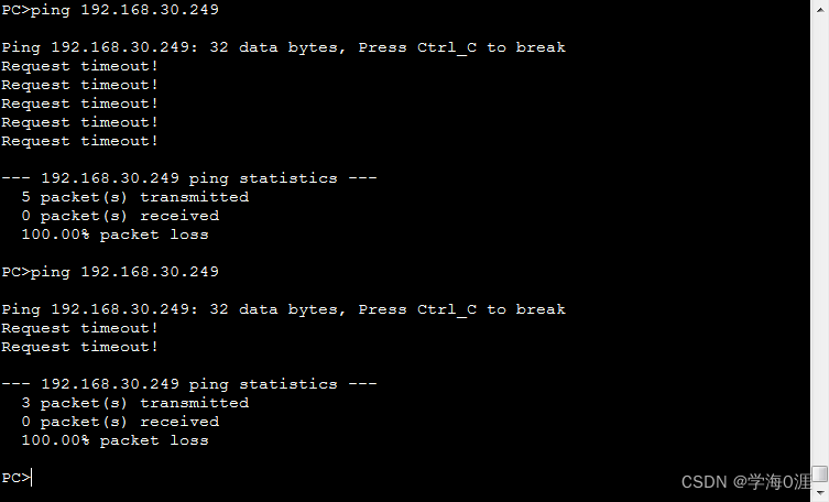
12、部分功能测试情况:
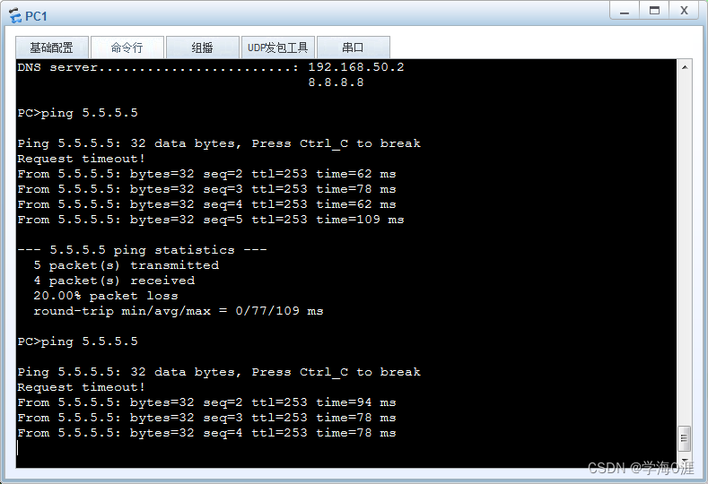


总结
这个实验涵盖的内容较多,实际上不仅仅局限于双机热备技术,差不多也花了大概一周的时间去做这个实验,排错时间使用了很多,也在CSDN借鉴了几位大神的想法。但有几个部分我也一直弄不明白:
1、wlan起来后,AC与AP的隧道已经打通,AP已经能获取AC的管理地址了,但STA池的地址不能自动获取。我在单独的设备不做其他配置,只做WLAN配置所有设备是能正常起来的。我查阅了很久的资料,说是ENSP这款软件的BUG,隧道转发不稳定导致的,如果有大神看到,希望能指点一下
2、DHCP服务器时好时坏,有时候不能获取地址。但我在抓包时未发现STP环路的情况,但有时会PING不通DHCP服务器出接口地址