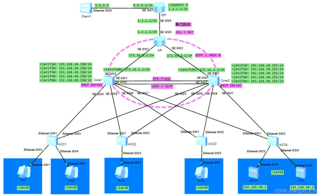
各设备的端口配置如下:
按照网络拓扑图,各设备按照从上到下的顺序配置如下:

①ISP各端口参数配置如下:
[ISP]display ip interface brief

Interface                         IP Address/Mask      Physical   Protocol
GigabitEthernet0/0/0              1.1.1.2/24           up         up
GigabitEthernet0/0/1              5.5.5.1/24           up         up
LoopBack0                         2.2.2.2/24           up         up(s)


②AR各端口参数配置如下:
[AR]display ip interface brief

Interface                         IP Address/Mask      Physical   Protocol
GigabitEthernet0/0/0              1.1.1.1/24           up         up
GigabitEthernet0/0/1              172.16.1.2/24        up         up
GigabitEthernet0/0/2              172.16.2.2/24        up         up


③Core1各端口参数配置如下:
[Core1]display ip interface brief

Interface                         IP Address/Mask      Physical   Protocol
Vlanif10                          192.168.10.250/24    up         up
Vlanif20                          192.168.20.250/24    up         up
Vlanif30                          192.168.30.250/24    up         up
Vlanif40                          192.168.40.250/24    up         up
Vlanif50                          192.168.50.250/24    up         up
Vlanif100                         172.16.1.1/24        up         up

[Core1]interface Eth-Trunk 1   //创建链路聚合
[Core1-Eth-Trunk1]port link-type trunk
[Core1-Eth-Trunk1]port trunk allow-pass vlan 10 20 30 40 50
[Core1-Eth-Trunk1]mode lacp-static  //配置模式为LACP
[Core1-Eth-Trunk1]trunkport GigabitEthernet 0/0/1 to 0/0/2    //捆绑接口

[Core1]interface GigabitEthernet0/0/3
[Core1-GigabitEthernet0/0/3]port link-type access
[Core1-GigabitEthernet0/0/3]port default vlan 100

[Core1]interface GigabitEthernet0/0/4
[Core1-GigabitEthernet0/0/4]port link-type trunk
[Core1-GigabitEthernet0/0/4]port trunk allow-pass vlan 10 20

[Core1]interface GigabitEthernet0/0/5
[Core1-GigabitEthernet0/0/5]port link-type trunk
[Core1-GigabitEthernet0/0/5]port trunk allow-pass vlan 30

[Core1]interface GigabitEthernet0/0/6
[Core1-GigabitEthernet0/0/6]port link-type trunk
[Core1-GigabitEthernet0/0/6]port trunk allow-pass vlan 40

[Core1]interface GigabitEthernet0/0/7
[Core1-GigabitEthernet0/0/7]port link-type trunk
[Core1-GigabitEthernet0/0/7]port trunk allow-pass vlan 50


④Core2各端口参数配置如下:
[Coer2]vlan batch 10 20 30 40 50 101

[Coer2]display ip interface brief

Interface                         IP Address/Mask      Physical   Protocol
Vlanif10                          192.168.10.251/24    up         up
Vlanif20                          192.168.20.251/24    up         up
Vlanif30                          192.168.30.251/24    up         up
Vlanif40                          192.168.40.251/24    up         up
Vlanif50                          192.168.50.251/24    up         up
Vlanif101                         172.16.2.1/24        up         up

[Coer2]interface Eth-Trunk 1
[Coer2-Eth-Trunk1]port link-type trunk
[Coer2-Eth-Trunk1]port trunk allow-pass vlan 10 20 30 40 50
[Coer2-Eth-Trunk1]mode lacp-static
[Coer2-Eth-Trunk1]trunkport GigabitEthernet 0/0/1 to 0/0/2

[Core2]interface GigabitEthernet0/0/3
[Core2-GigabitEthernet0/0/3]port link-type access
[Core2-GigabitEthernet0/0/3]port default vlan 101

[Core2]interface GigabitEthernet0/0/4
[Core2-GigabitEthernet0/0/4]port link-type trunk
[Core2-GigabitEthernet0/0/4]port trunk allow-pass vlan 10 20

[Core2]interface GigabitEthernet0/0/5
[Core2-GigabitEthernet0/0/5]port link-type trunk
[Core2-GigabitEthernet0/0/5]port trunk allow-pass vlan 30

[Core2]interface GigabitEthernet0/0/6
[Core2-GigabitEthernet0/0/6]port link-type trunk
[Core2-GigabitEthernet0/0/6]port trunk allow-pass vlan 40

[Core2]interface GigabitEthernet0/0/7
[Core2-GigabitEthernet0/0/7]port link-type trunk
[Core2-GigabitEthernet0/0/7]port trunk allow-pass vlan 50


⑤ACC1各端口参数配置如下:
[ACC1]vlan batch 10 20

[ACC1]interface Ethernet0/0/1
[ACC1-Ethernet0/0/1]port link-type trunk
[ACC1-Ethernet0/0/1]port trunk allow-pass vlan 10 20

[ACC1]interface Ethernet0/0/2
[ACC1-Ethernet0/0/2]port link-type trunk
[ACC1-Ethernet0/0/2]port trunk allow-pass vlan 10 20

[ACC1]interface Ethernet0/0/3
[ACC1-Ethernet0/0/3]port link-type access
[ACC1-Ethernet0/0/3]port default vlan 10

[ACC1]interface Ethernet0/0/4
[ACC1-Ethernet0/0/4]port link-type access
[ACC1-Ethernet0/0/4]port default vlan 20


⑥ACC2各端口参数配置如下:
[ACC2]vlan batch 30

[ACC2]interface Ethernet0/0/1
[ACC2-Ethernet0/0/1]port link-type trunk
[ACC2-Ethernet0/0/1]port trunk allow-pass vlan 30

[ACC2]interface Ethernet0/0/2
[ACC2-Ethernet0/0/2]port link-type trunk
[ACC2-Ethernet0/0/2]port trunk allow-pass vlan 30

[ACC2]interface Ethernet0/0/3
[ACC2-Ethernet0/0/3]port link-type access
[ACC2-Ethernet0/0/3]port default vlan 30


⑦ACC3各端口参数配置如下:
[ACC3]vlan batch 40

[ACC3]interface Ethernet0/0/1
[ACC3-Ethernet0/0/1]port link-type trunk
[ACC3-Ethernet0/0/1]port trunk allow-pass vlan 40

[ACC3]interface Ethernet0/0/2
[ACC3-Ethernet0/0/2]port link-type trunk
[ACC3-Ethernet0/0/2]port trunk allow-pass vlan 40

[ACC3]interface Ethernet0/0/3
[ACC3-Ethernet0/0/3]port link-type access
[ACC3-Ethernet0/0/3]port default vlan 40


⑧ACC4各端口参数配置如下:
[ACC4]vlan batch 50

[ACC4]interface Ethernet0/0/1
[ACC4-Ethernet0/0/1]port link-type trunk
[ACC4-Ethernet0/0/1]port trunk allow-pass vlan 50

[ACC4]interface Ethernet0/0/2
[ACC4-Ethernet0/0/2]port link-type trunk
[ACC4-Ethernet0/0/2]port trunk allow-pass vlan 50

[ACC4]interface Ethernet0/0/3
[ACC4-Ethernet0/0/3]port link-type access
[ACC4-Ethernet0/0/3]port default vlan 50

[ACC4]interface Ethernet0/0/4
[ACC4-Ethernet0/0/4]port link-type access
[ACC4-Ethernet0/0/4]port default vlan 50
配置多生成树MSTP防止网络环路
①Core1配置多生成树MSTP
[Core1]stp enable  //开启生成树
[Core1]stp mode mstp   //模式为多生成树
[Core1]stp region-configuration  //生成树域的配置
[Core1-mst-region]region-name ACC_To_Core  //配置相同域名
[Core1-mst-region]instance 1 vlan 10  //配置实例1与vlan10绑定
[Core1-mst-region]instance 2 vlan 20  //配置实例2与vlan20绑定
[Core1-mst-region]instance 3 vlan 30  //配置实例3与vlan30绑定
[Core1-mst-region]instance 4 vlan 40  //配置实例4与vlan40绑定
[Core1-mst-region]instance 5 vlan 50  //配置实例5与vlan50绑定
[Core1-mst-region]active region-configuration  //激活生成树域

[Core1]stp instance 1 root primary      //Core1配置为实例1的主根
[Core1]stp instance 2 root secondary    //Core1配置为实例2的备根
[Core1]stp instance 3 root primary      //Core1配置为实例3的主根
[Core1]stp instance 4 root secondary    //Core1配置为实例4的备根
[Core1]stp instance 5 root primary      //Core1配置为实例5的主根

②Core2配置多生成树MSTP
[Coer2]stp enable
[Coer2]stp mode mstp
[Coer2]stp region-configuration
[Coer2-mst-region]region-name ACC_To_Core  //与Core1上配置相同名称
[Coer2-mst-region]instance 1 vlan 10
[Coer2-mst-region]instance 2 vlan 20
[Coer2-mst-region]instance 3 vlan 30
[Coer2-mst-region]instance 4 vlan 40
[Coer2-mst-region]instance 5 vlan 50
[Coer2-mst-region]active region-configuration

[Coer2]stp instance 1 root secondary     //Core2配置为实例1的备根
[Coer2]stp instance 2 root primary       //Core2配置为实例2的主根
[Coer2]stp instance 3 root secondary     //Core2配置为实例3的备根
[Coer2]stp instance 4 root primary       //Core2配置为实例4的主根
[Coer2]stp instance 5 root secondary     //Core2配置为实例5的备根

③ACC1配置多生成树MSTP,ACC2、ACC3、ACC4同样进行下面相同配置
[ACC1]stp enable
[ACC1]stp mode mstp
[ACC1]stp region-configuration
[ACC1-mst-region]region-name ACC_To_Core   //与Core1上配置相同名称
[ACC1-mst-region]instance 1 vlan 10
[ACC1-mst-region]instance 2 vlan 20
[ACC1-mst-region]instance 3 vlan 30
[ACC1-mst-region]instance 4 vlan 40
[ACC1-mst-region]instance 5 vlan 50
[ACC1-mst-region]active region-configuration
将Core1和Core2聚合成一台逻辑上的交换机,实现设备冗余
①在Core1上配置如下:
//vlan10从Core1上通过
[Core1]interface Vlanif 10
[Core1-Vlanif10]vrrp vrid 1 virtual-ip 192.168.10.254    //VRRP组,VRID为1,虚拟IP为192.168.10.254
[Core1-Vlanif10]vrrp vrid 1 priority 120  //配置优先级为120(默认为100),优先级越大,就会从Core1通过
[Core1-Vlanif10]vrrp vrid 1 preempt-mode timer delay 20  //抢占模式为延时抢占,时间为20秒

//vlan20从Core2上通过,所以Core1上不需要配置优先级和抢占模式
[Core1]interface Vlanif 20
[Core1-Vlanif20]vrrp vrid 2 virtual-ip 192.168.20.254

//vlan30配置与vlan10相同
[Core1]interface Vlanif 30
[Core1-Vlanif30]vrrp vrid 3 virtual-ip 192.168.30.254
[Core1-Vlanif30]vrrp vrid 3 priority 120
[Core1-Vlanif30]vrrp vrid 3 preempt-mode timer delay 20

//vlan40配置与vlan20相同
[Core1]interface Vlanif 40
[Core1-Vlanif40]vrrp vrid 4 virtual-ip 192.168.40.254

//vlan50配置与vlan10相同
[Core1]interface Vlanif 50
[Core1-Vlanif50]vrrp vrid 5 virtual-ip 192.168.50.254
[Core1-Vlanif50]vrrp vrid 5 priority 120
[Core1-Vlanif50]vrrp vrid 5 preempt-mode timer delay 20


②在Core2上配置如下:
[Coer2]interface Vlanif 10
[Coer2-Vlanif10]vrrp vrid 1 virtual-ip 192.168.10.254

[Coer2]interface Vlanif 20
[Coer2-Vlanif20]vrrp vrid 2 virtual-ip 192.168.20.254
[Coer2-Vlanif20]vrrp vrid 2 priority 120
[Coer2-Vlanif20]vrrp vrid 2 preempt-mode timer delay 20

[Coer2]interface Vlanif 30
[Coer2-Vlanif30]vrrp vrid 3 virtual-ip 192.168.30.254

[Coer2]interface Vlanif 40
[Coer2-Vlanif40]vrrp vrid 4 virtual-ip 192.168.40.254
[Coer2-Vlanif40]vrrp vrid 4 priority 120
[Coer2-Vlanif40]vrrp vrid 4 preempt-mode timer delay 20

[Coer2]interface Vlanif 50
[Coer2-Vlanif50]vrrp vrid 5 virtual-ip 192.168.50.254
Core1和Core2使能DHCP分配地址
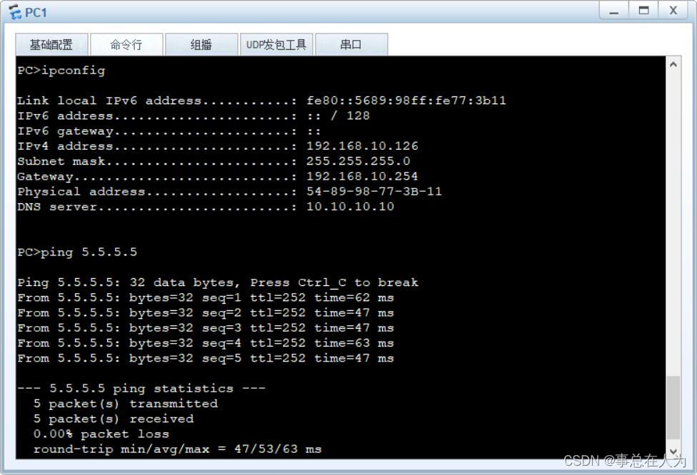
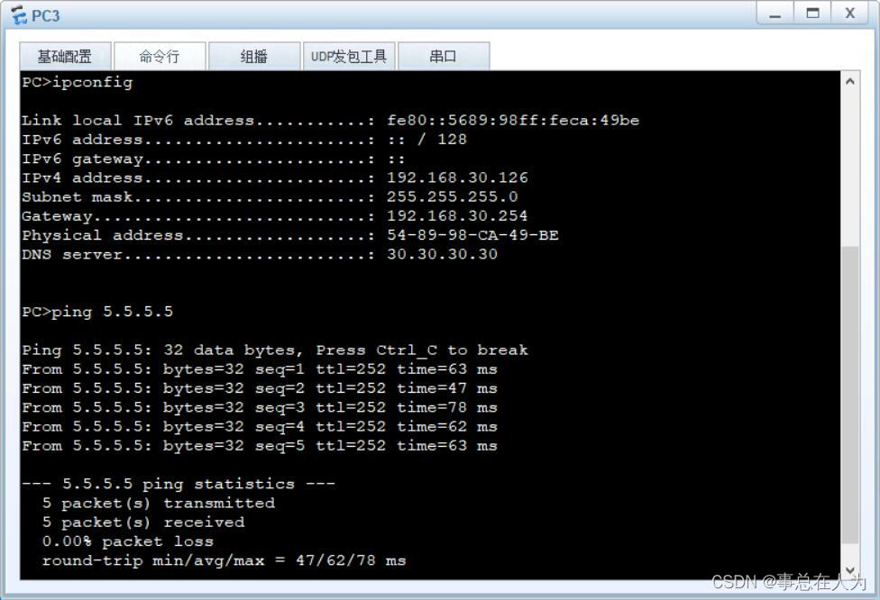
Core1上分配1到126地址段,Core2上分配到127到253地址段
①Core1上具体配置如下:
[Core1]dhcp enable

//创建vlan10的地址池
[Core1]ip pool vlan10   //地址池名称为vlan10
[Core1-ip-pool-vlan10]gateway-list 192.168.10.254   //配置网关
[Core1-ip-pool-vlan10]network 192.168.10.0 mask 24   //配置网段
[Core1-ip-pool-vlan10]dns-list 10.10.10.10   //DNS地址
[Core1-ip-pool-vlan10]excluded-ip-address 192.168.10.127 192.168.10.253  //Core1上排除127到253地址段
[Core1-ip-pool-vlan10]lease 10  //地址租期为10天

//vlan10开启全局地址分配
[Core1]interface Vlanif 10
[Core1-Vlanif10]dhcp select global

//同样为vlan20分配创建地址池
[Core1]ip pool vlan20
[Core1-ip-pool-vlan20]gateway-list 192.168.20.254
[Core1-ip-pool-vlan20]network 192.168.20.0 mask 24
[Core1-ip-pool-vlan20]dns-list 20.20.20.20
[Core1-ip-pool-vlan20]excluded-ip-address 192.168.20.127 192.168.20.253
[Core1-ip-pool-vlan20]lease day 10

[Core1]interface Vlanif 20
[Core1-Vlanif20]dhcp select global

//同样为vlan30分配创建地址池
[Core1]ip pool vlan30
[Core1-ip-pool-vlan30]gateway-list 192.168.30.254
[Core1-ip-pool-vlan30]network 192.168.30.0 mask 24
[Core1-ip-pool-vlan30]dns-list 30.30.30.30
[Core1-ip-pool-vlan30]excluded-ip-address 192.168.30.127 192.168.30.253
[Core1-ip-pool-vlan30]lease day 10

[Core1]interface Vlanif 30
[Core1-Vlanif30]dhcp select global

//同样为vlan40分配创建地址池
[Core1]ip pool vlan40
[Core1-ip-pool-vlan40]gateway-list 192.168.40.254
[Core1-ip-pool-vlan40]network 192.168.40.0 mask 24
[Core1-ip-pool-vlan40]dns-list 40.40.40.40
[Core1-ip-pool-vlan40]excluded-ip-address 192.168.40.127 192.168.40.253
[Core1-ip-pool-vlan40]lease day 10

[Core1]interface Vlanif 40
[Core1-Vlanif40]dhcp select global

②Core2上具体配置如下:
[Core2]dhcp enable

//为vlan10分配创建地址池
[Coer2]ip pool vlan10
[Coer2-ip-pool-vlan10]gateway-list 192.168.10.254
[Coer2-ip-pool-vlan10]network 192.168.10.0 mask 24
[Coer2-ip-pool-vlan10]dns-list 10.10.10.10
[Coer2-ip-pool-vlan10]excluded-ip-address 192.168.10.1 192.168.10.126
[Coer2-ip-pool-vlan10]lease day 10

[Coer2]interface Vlanif 10
[Coer2-Vlanif10]dhcp select global

//同样为vlan20分配创建地址池
[Coer2]ip pool vlan20
[Coer2-ip-pool-vlan20]gateway-list 192.168.20.254
[Coer2-ip-pool-vlan20]network 192.168.20.0 mask 24
[Coer2-ip-pool-vlan20]dns-list 20.20.20.20
[Coer2-ip-pool-vlan20]excluded-ip-address 192.168.20.1 192.168.20.126
[Coer2-ip-pool-vlan20]lease day 10

[Coer2]interface Vlanif 20
[Coer2-Vlanif20]dhcp select global

//同样为vlan30分配创建地址池
[Coer2]ip pool vlan30
[Coer2-ip-pool-vlan30]gateway-list 192.168.30.254
[Coer2-ip-pool-vlan30]network 192.168.30.0 mask 24
[Coer2-ip-pool-vlan30]dns-list 30.30.30.30
[Coer2-ip-pool-vlan30]excluded-ip-address 192.168.30.1 192.168.30.126
[Coer2-ip-pool-vlan30]lease day 10

[Coer2]interface Vlanif 30
[Coer2-Vlanif30]dhcp select global

//同样为vlan40分配创建地址池
[Coer2]ip pool vlan40
[Coer2-ip-pool-vlan40]gateway-list 192.168.40.254
[Coer2-ip-pool-vlan40]network 192.168.40.0 mask 24
[Coer2-ip-pool-vlan40]dns-list 40.40.40.40
[Coer2-ip-pool-vlan40]excluded-ip-address 192.168.40.1 192.168.40.126
[Coer2-ip-pool-vlan40]lease day 10

[Coer2]interface Vlanif 40
[Coer2-Vlanif40]dhcp select global

③查看VRRP的状态
[Core1]display vrrp brief
VRID  State        Interface		Type     Virtual IP
----------------------------------------------------------------
1     Master       Vlanif10		Normal   192.168.10.254
2     Backup       Vlanif20		Normal   192.168.20.254
3     Master       Vlanif30		Normal   192.168.30.254
4     Backup       Vlanif40		Normal   192.168.40.254
5     Backup       Vlanif50		Normal   192.168.50.254
----------------------------------------------------------------
Total:5     Master:2     Backup:3     Non-active:0
OSPF实现动态路由
①Core1配置如下:
[Core1]ospf 1 router-id 172.16.1.1    //OSPF进程号为1,路由ID为172.16.1.1
[Core1-ospf-1]area 0   //配置主干区域
[Core1-ospf-1-area-0.0.0.0]network 172.16.1.1 0.0.0.0   //精准宣告172.16.1.1
[Core1-ospf-1-area-0.0.0.0]network 192.168.10.0 0.0.0.255   //宣告192.168.10.0网段
[Core1-ospf-1-area-0.0.0.0]network 192.168.20.0 0.0.0.255   //宣告192.168.20.0网段
[Core1-ospf-1-area-0.0.0.0]network 192.168.30.0 0.0.0.255   //宣告192.168.30.0网段
[Core1-ospf-1-area-0.0.0.0]network 192.168.40.0 0.0.0.255   //宣告192.168.40.0网段
[Core1-ospf-1-area-0.0.0.0]network 192.168.50.0 0.0.0.255   //宣告192.168.50.0网段

②Core2配置如下:
[Coer2]ospf 1 router-id 172.16.2.1   //OSPF进程号为1,路由ID为172.16.2.1
[Coer2-ospf-1]area 0  //配置主干区域
[Coer2-ospf-1-area-0.0.0.0]network 172.16.2.1 0.0.0.0   //精准宣告172.16.2.1
[Coer2-ospf-1-area-0.0.0.0]network 192.168.10.0 0.0.0.255
[Coer2-ospf-1-area-0.0.0.0]network 192.168.20.0 0.0.0.255
[Coer2-ospf-1-area-0.0.0.0]network 192.168.30.0 0.0.0.255
[Coer2-ospf-1-area-0.0.0.0]network 192.168.40.0 0.0.0.255
[Coer2-ospf-1-area-0.0.0.0]network 192.168.50.0 0.0.0.255

③AR配置如下:
[AR]ospf 1 router-id 1.1.1.1
[AR-ospf-1]area 0
[AR-ospf-1-area-0.0.0.0]network 172.16.1.2 0.0.0.0   //精准宣告172.16.1.2
[AR-ospf-1-area-0.0.0.0]network 172.16.2.2 0.0.0.0   //精准宣告172.16.2.2

④查看OSPF信息
[AR]display ospf peer

		 OSPF Process 1 with Router ID 1.1.1.1
			 Neighbors

	 Area 0.0.0.0 interface 172.16.1.2(GigabitEthernet0/0/1)'s neighbors
	 Router ID: 172.16.1.1       Address: 172.16.1.1
	   State: Full  Mode:Nbr is  Master  Priority: 1
	   DR: 172.16.1.1  BDR: 172.16.1.2  MTU: 0
	   Dead timer due in 40  sec
	   Retrans timer interval: 5
	   Neighbor is up for 00:01:28
	   Authentication Sequence: [ 0 ]

			 Neighbors

	 Area 0.0.0.0 interface 172.16.2.2(GigabitEthernet0/0/2)'s neighbors
	 Router ID: 172.16.2.1       Address: 172.16.2.1
	   State: Full  Mode:Nbr is  Master  Priority: 1
	   DR: 172.16.2.1  BDR: 172.16.2.2  MTU: 0
	   Dead timer due in 28  sec
	   Retrans timer interval: 5
	   Neighbor is up for 00:01:15
	   Authentication Sequence: [ 0 ]

⑤查看OSPF的链路数据库
[AR]display ospf lsdb

		 OSPF Process 1 with Router ID 1.1.1.1
			 Link State Database

					 Area: 0.0.0.0
	 Type      LinkState ID    AdvRouter          Age  Len   Sequence   Metric
	 Router    172.16.1.1      172.16.1.1         149  120   8000001E       1
	 Router    172.16.2.1      172.16.2.1         133  132   80000014       1
	 Router    1.1.1.1         1.1.1.1            138  48    80000006       1
	 Network   172.16.1.1      172.16.1.1         149  32    80000002       0
	 Network   192.168.50.250  172.16.1.1         480  32    80000002       0
	 Network   192.168.10.250  172.16.1.1         530  32    80000002       0
	 Network   192.168.30.250  172.16.1.1         505  32    80000002       0
	 Network   192.168.40.250  172.16.1.1         492  32    80000002       0
	 Network   172.16.2.1      172.16.2.1         133  32    80000002       0
	 Network   192.168.20.250  172.16.1.1         516  32    80000002       0

⑥查看OSPF路由表
[AR]display ip routing-table protocol ospf


⑦为了保证主干区域的安全性,可以基于OSPF主干区域基于区域认证
分别在主干区域的Core1、Core2和AR上配置如下:
[Core1]ospf 1
[Core1-ospf-1]area 0
[Core1-ospf-1-area-0.0.0.0]authentication-mode hmac-md5 1 cipher 123456   //加密方式为HMAC-MD5,密文显示密码

[Core2]ospf 1
[Core2-ospf-1]area 0
[Core2-ospf-1-area-0.0.0.0]authentication-mode hmac-md5 1 cipher 123456

[AR]ospf 1
[AR-ospf-1]area 0
[AR-ospf-1-area-0.0.0.0]authentication-mode hmac-md5 1 cipher 123456
配置NAT Server实现访问互联网
①AR上配置如下:
[AR]ip route-static 0.0.0.0 0 1.1.1.2    //配置出口默认静态路由
[AR-ospf-1]default-route-advertise always   //将默认静态路由通告到OSPF内实现路由可达

此处可在在Core1和Core2上查看OSPF引用了一条如下路由条目
[Core1]display ip routing-table protocol ospf

	Destination/Mask	Proto		Pre	Cost	Flags	NextHop	    Interface
		0.0.0.0/0	    O_ASE		150	 1	       D	172.16.1.2	Vlanif100

②在AR上配置访问数据控制列表
[AR]acl 2000
[AR-acl-basic-2000]rule 5 permit source any   //创建规则为5,允许所有数据通过

//如果指定vlan10、vlan20、vlan30、vlan40允许通过,vlan50不允许通过,配置如下:
[AR-acl-basic-2000]rule permit source 192.168.10.0 0.0.0.255
[AR-acl-basic-2000]rule permit source 192.168.20.0 0.0.0.255
[AR-acl-basic-2000]rule permit source 192.168.30.0 0.0.0.255
[AR-acl-basic-2000]rule permit source 192.168.40.0 0.0.0.255
[AR-acl-basic-2000]rule deny source 192.168.50.0 0.0.0.255    //不允许192.168.50.0的地址段通过

③在AR出口接口配置NAT
[AR]interface GigabitEthernet 0/0/0
[AR-GigabitEthernet0/0/0]nat outbound 2000
[AR-GigabitEthernet0/0/0]nat server protocol tcp global current-interface www inside 192.168.50.1 www
[AR-GigabitEthernet0/0/0]nat server protocol tcp global current-interface ftp inside 192.168.50.2 ftp

[AR]nat alg ftp enable   //开启FTP的NAT ALG
结果测试: