1 平台条件
硬件:nrf52840
软件:sdk17.0
2 QSPI概述
QSPI 外设支持使用 SPI 与外部闪存设备进行通信
此处列出了 QSPI 外设的主要特性:
• 单/双/四通道 SPI 输入/输出
• 2–32 MHz 可配置时钟频率
• 从/到外部闪存的单字读/写访问
• 用于块读写传输的 EasyDMA
• 高达 16 MB/秒的 EasyDMA 读取速率
• 就地执行 (XIP),用于直接从外部闪存执行程序
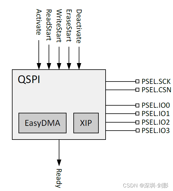
在 Nordic nRF52/nRF53 系列上,QSPI 可以支持两种不同的模式。
Flash / XIP操作(需要遵循flash协议)
发送自定义指令(限制使用QSPI上的1-wire发送数据)。
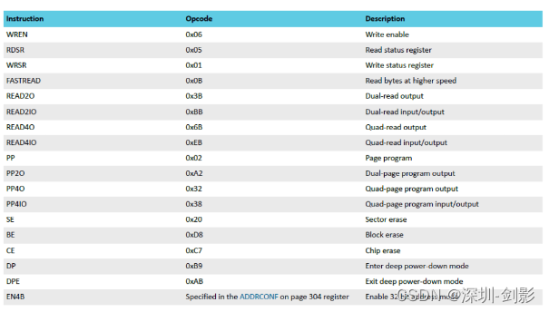
在指令集上,它支持与外部闪存设备的操作码。
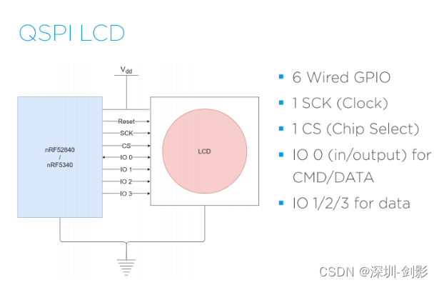
1.1 用于 LCD 的 QSPI 接口
基本上,QSPI 接口有 6 个 GPIO 引脚。
使用屏幕: hannstar 360×360 with GalaxyCore Controller resolution for testing.
2 代码设置
2.1 初始化
初始化 QSPI 模块
将所有 6 个 GPIO 引脚配置为高驱动输出。
#define LCD_QSPI_RESET_PIN NRF_GPIO_PIN_MAP(0,27)
#define LCD_QSPI_CSN_PIN   NRF_GPIO_PIN_MAP(0,26)
#define LCD_QSPI_SCK_PIN   NRF_GPIO_PIN_MAP(0,02)
#define LCD_QSPI_IO0_PIN   NRF_GPIO_PIN_MAP(1,15)
#define LCD_QSPI_IO1_PIN   NRF_GPIO_PIN_MAP(1,14)
#define LCD_QSPI_IO2_PIN   NRF_GPIO_PIN_MAP(1,13)
#define LCD_QSPI_IO3_PIN   NRF_GPIO_PIN_MAP(1,12)

static void config_qspi_pin_high_drive(void)
{


        nrf_gpio_cfg(
                LCD_QSPI_SCK_PIN,
                NRF_GPIO_PIN_DIR_INPUT,
                NRF_GPIO_PIN_INPUT_CONNECT,
                NRF_GPIO_PIN_PULLDOWN,
                NRF_GPIO_PIN_H0H1,
                NRF_GPIO_PIN_SENSE_HIGH);
        nrf_gpio_cfg(
                LCD_QSPI_CSN_PIN,
                NRF_GPIO_PIN_DIR_INPUT,
                NRF_GPIO_PIN_INPUT_DISCONNECT,
                NRF_GPIO_PIN_NOPULL,
                NRF_GPIO_PIN_H0H1,
                NRF_GPIO_PIN_NOSENSE);

        nrf_gpio_cfg(
                LCD_QSPI_IO0_PIN,
                NRF_GPIO_PIN_DIR_INPUT,
                NRF_GPIO_PIN_INPUT_DISCONNECT,
                NRF_GPIO_PIN_PULLDOWN,
                NRF_GPIO_PIN_H0H1,
                NRF_GPIO_PIN_NOSENSE);

        nrf_gpio_cfg(
                LCD_QSPI_IO1_PIN,
                NRF_GPIO_PIN_DIR_INPUT,
                NRF_GPIO_PIN_INPUT_DISCONNECT,
                NRF_GPIO_PIN_PULLDOWN,
                NRF_GPIO_PIN_H0H1,
                NRF_GPIO_PIN_NOSENSE);

        nrf_gpio_cfg(
                LCD_QSPI_IO2_PIN,
                NRF_GPIO_PIN_DIR_INPUT,
                NRF_GPIO_PIN_INPUT_DISCONNECT,
                NRF_GPIO_PIN_PULLDOWN,
                NRF_GPIO_PIN_H0H1,
                NRF_GPIO_PIN_NOSENSE);

        nrf_gpio_cfg(
                LCD_QSPI_IO3_PIN,
                NRF_GPIO_PIN_DIR_INPUT,
                NRF_GPIO_PIN_INPUT_DISCONNECT,
                NRF_GPIO_PIN_PULLDOWN,
                NRF_GPIO_PIN_H0H1,
                NRF_GPIO_PIN_NOSENSE);
}
LCD demo 320×240 @ nRF52840 之后,我想描述如何使用 QSPI 接口驱动更大的 LCD 显示器,例如 360 x 360 分辨率 @ nRF52840。
QSPI 四路串行外设接口
QSPI 外设支持使用 SPI 与外部闪存设备进行通信。
此处列出了 QSPI 外设的主要特性:
• 单/双/四通道 SPI 输入/输出
• 2–32 MHz 可配置时钟频率
• 从/到外部闪存的单字读/写访问
• 用于块读写传输的 EasyDMA
• 高达 16 MB/秒的 EasyDMA 读取速率
• 就地执行 (XIP),用于直接从外部闪存执行程序
在 Nordic nRF52/nRF53 系列上,QSPI 可以支持两种不同的模式。
Flash / XIP操作(需要遵循flash协议)
发送自定义指令(限制使用QSPI上的1-wire发送数据)。
在指令集上,它支持与外部闪存设备的操作码。
用于 LCD 的 QSPI 接口
基本上,QSPI 接口有 6 个 GPIO 引脚。
在这篇博客中,我将使用显示器制造商的瀚宇360×360 和GalaxyCore Controller 分辨率进行测试。
初始化 QSPI 模块
将所有 6 个 GPIO 引脚配置为高驱动输出。
#define LCD_QSPI_RESET_PIN NRF_GPIO_PIN_MAP(0,27)
#define LCD_QSPI_CSN_PIN   NRF_GPIO_PIN_MAP(0,26)
#define LCD_QSPI_SCK_PIN   NRF_GPIO_PIN_MAP(0,02)
#define LCD_QSPI_IO0_PIN   NRF_GPIO_PIN_MAP(1,15)
#define LCD_QSPI_IO1_PIN   NRF_GPIO_PIN_MAP(1,14)
#define LCD_QSPI_IO2_PIN   NRF_GPIO_PIN_MAP(1,13)
#define LCD_QSPI_IO3_PIN   NRF_GPIO_PIN_MAP(1,12)

static void config_qspi_pin_high_drive(void)
{


        nrf_gpio_cfg(
                LCD_QSPI_SCK_PIN,
                NRF_GPIO_PIN_DIR_INPUT,
                NRF_GPIO_PIN_INPUT_CONNECT,
                NRF_GPIO_PIN_PULLDOWN,
                NRF_GPIO_PIN_H0H1,
                NRF_GPIO_PIN_SENSE_HIGH);
        nrf_gpio_cfg(
                LCD_QSPI_CSN_PIN,
                NRF_GPIO_PIN_DIR_INPUT,
                NRF_GPIO_PIN_INPUT_DISCONNECT,
                NRF_GPIO_PIN_NOPULL,
                NRF_GPIO_PIN_H0H1,
                NRF_GPIO_PIN_NOSENSE);

        nrf_gpio_cfg(
                LCD_QSPI_IO0_PIN,
                NRF_GPIO_PIN_DIR_INPUT,
                NRF_GPIO_PIN_INPUT_DISCONNECT,
                NRF_GPIO_PIN_PULLDOWN,
                NRF_GPIO_PIN_H0H1,
                NRF_GPIO_PIN_NOSENSE);

        nrf_gpio_cfg(
                LCD_QSPI_IO1_PIN,
                NRF_GPIO_PIN_DIR_INPUT,
                NRF_GPIO_PIN_INPUT_DISCONNECT,
                NRF_GPIO_PIN_PULLDOWN,
                NRF_GPIO_PIN_H0H1,
                NRF_GPIO_PIN_NOSENSE);

        nrf_gpio_cfg(
                LCD_QSPI_IO2_PIN,
                NRF_GPIO_PIN_DIR_INPUT,
                NRF_GPIO_PIN_INPUT_DISCONNECT,
                NRF_GPIO_PIN_PULLDOWN,
                NRF_GPIO_PIN_H0H1,
                NRF_GPIO_PIN_NOSENSE);

        nrf_gpio_cfg(
                LCD_QSPI_IO3_PIN,
                NRF_GPIO_PIN_DIR_INPUT,
                NRF_GPIO_PIN_INPUT_DISCONNECT,
                NRF_GPIO_PIN_PULLDOWN,
                NRF_GPIO_PIN_H0H1,
                NRF_GPIO_PIN_NOSENSE);
}
初始化 QSPI 模块并将其配置为 24 位地址/32MHz 时钟。
void qspi_lcd_GC9c01_init(void)
{


        if (!m_is_qspi_init)
        {


                uint32_t err_code;
                nrf_drv_qspi_config_t qspi_lcd_config = NRF_DRV_QSPI_DEFAULT_CONFIG;
                //config.phy_if.sck_freq  = NRF_QSPI_FREQ_32MDIV1;        //NRF_QSPI_FREQ_32MDIV8; //32MHz
                qspi_lcd_config.phy_if.sck_freq  = NRF_QSPI_FREQ_32MDIV1;        //NRF_QSPI_FREQ_32MDIV8; //32MHz
                //qspi_lcd_config.phy_if.sck_freq  = NRF_QSPI_FREQ_32MDIV8;//NRF_QSPI_FREQ_32MDIV8; //8MHz

                qspi_lcd_config.pins.csn_pin     = LCD_QSPI_CSN_PIN;
                qspi_lcd_config.pins.sck_pin     = LCD_QSPI_SCK_PIN;
                qspi_lcd_config.pins.io0_pin     = LCD_QSPI_IO0_PIN;
                qspi_lcd_config.pins.io1_pin     = LCD_QSPI_IO1_PIN;
                qspi_lcd_config.pins.io2_pin     = LCD_QSPI_IO2_PIN;
                qspi_lcd_config.pins.io3_pin     = LCD_QSPI_IO3_PIN;

                err_code = nrf_drv_qspi_init(&qspi_lcd_config, qspi_lcd_handler, NULL);
                APP_ERROR_CHECK(err_code);

                NRF_LOG_INFO("QSPI LCD Init");
                NRF_QSPI->IFCONFIG0 |= (QSPI_IFCONFIG0_PPSIZE_512Bytes << QSPI_IFCONFIG0_PPSIZE_Pos);

                m_is_qspi_init = true;
        }
        else
        {


                NRF_LOG_ERROR("QSPI LCD has already initialized!");
                APP_ERROR_CHECK(-1);
        }
}
2.2 读写操作
基本上,LCD 上有 2 个操作。
LCD 命令代码(例如 LCD 初始化代码)。
LCD Data write(将数据写入LCD屏)。
(1)LCD命令模式
(2)LCD写命令
static uint32_t drv_GC9c01_bus_writeCmd(const uint8_t cmd)
{


        return send_qspi_cinstr_w0d(cmd);
}
static uint32_t drv_GC9c01_bus_writeCmdByte(const uint8_t cmd, const uint8_t data)
{


        uint32_t err_code = NRF_SUCCESS;
        err_code  = send_qspi_cinstr_w1d(cmd, data);
        return err_code;
}
(3)LCD初始化代码
static void configure_lcd()
{


        drv_GC9c01_bus_writeCmd(0xfe);
        drv_GC9c01_bus_writeCmd(0xef);

        drv_GC9c01_bus_writeCmdByte(0x80, 0x11);
        drv_GC9c01_bus_writeCmdByte(0x81, 0x70);

        drv_GC9c01_bus_writeCmdByte(0x82, 0x09);
        drv_GC9c01_bus_writeCmdByte(0x83, 0x03);

        drv_GC9c01_bus_writeCmdByte(0x84, 0x20);
        drv_GC9c01_bus_writeCmdByte(0x85, 0x42);

        drv_GC9c01_bus_writeCmdByte(0x86, 0xfc);
        drv_GC9c01_bus_writeCmdByte(0x87, 0x09);

        drv_GC9c01_bus_writeCmdByte(0x89, 0x10);
        drv_GC9c01_bus_writeCmdByte(0x8a, 0x4f);

        drv_GC9c01_bus_writeCmdByte(0x8c, 0x59);
        drv_GC9c01_bus_writeCmdByte(0x8d, 0x51);

        drv_GC9c01_bus_writeCmdByte(0x8e, 0xae);
        drv_GC9c01_bus_writeCmdByte(0x8f, 0xf3);

        drv_GC9c01_bus_writeCmdByte(0x36, 0x00);
        drv_GC9c01_bus_writeCmdByte(0x3a, 0x05);
        drv_GC9c01_bus_writeCmdByte(0xec, 0x77);

        uint8_t parmater1_buffer[] = {

    0x01, 0x80, 0x00, 0x00, 0x00, 0x00};
        send_qspi_cinstr_long_frame_word(0x74, parmater1_buffer, 6);
        drv_GC9c01_bus_writeCmdByte(0x98, 0x3e);
        drv_GC9c01_bus_writeCmdByte(0x99, 0x3e);
        drv_GC9c01_bus_writeCmdByte(0xc3, 0x2A);
        drv_GC9c01_bus_writeCmdByte(0xc4, 0x18);
        send_qspi_cinstr_w1d_2data(0xa1,0x01,0x04);
        send_qspi_cinstr_w1d_2data(0xa2,0x01,0x04);
        drv_GC9c01_bus_writeCmdByte(0xa9, 0x1c);

        send_qspi_cinstr_w1d_2data(0xa5,0x11,0x09);
        drv_GC9c01_bus_writeCmdByte(0xb9, 0x8a);
        drv_GC9c01_bus_writeCmdByte(0xa8, 0x5e);
        drv_GC9c01_bus_writeCmdByte(0xa7, 0x40);
        drv_GC9c01_bus_writeCmdByte(0xaf, 0x73);
        drv_GC9c01_bus_writeCmdByte(0xae, 0x44);
        drv_GC9c01_bus_writeCmdByte(0xad, 0x38);

        drv_GC9c01_bus_writeCmdByte(0xa3, 0x5d);

        drv_GC9c01_bus_writeCmdByte(0xc2, 0x02);

        drv_GC9c01_bus_writeCmdByte(0xc5, 0x11);


        drv_GC9c01_bus_writeCmdByte(0xc6, 0x0e);

        drv_GC9c01_bus_writeCmdByte(0xc7, 0x13);
        drv_GC9c01_bus_writeCmdByte(0xc8, 0x0d);
        drv_GC9c01_bus_writeCmdByte(0xcb, 0x02);

        send_qspi_cinstr_w1d_2data(0x7c,0xb6,0x26);
        drv_GC9c01_bus_writeCmdByte(0xac, 0x24);
        drv_GC9c01_bus_writeCmdByte(0xf6, 0x80);


        send_qspi_cinstr_w1d_2data(0xb5,0x09,0x09);
        send_qspi_cinstr_w1d_4data(0x60, 0x38,0x0b,0x5b,0x56);
        send_qspi_cinstr_w1d_4data(0x63, 0x3a,0xe0,0x5b,0x56);

        uint8_t parmater2_buffer[] = {

    0x38, 0x0d, 0x72, 0xdd, 0x5b, 0x56};
        send_qspi_cinstr_long_frame_word(0x64, parmater2_buffer, 6);
        uint8_t parmater3_buffer[] = {

    0x38, 0x11, 0x72, 0xe1, 0x5b, 0x56};
        send_qspi_cinstr_long_frame_word(0x66, parmater3_buffer, 6);
        uint8_t parmater4_buffer[] = {

    0x3b, 0x08, 0x08, 0x00, 0x08, 0x29,0x5b};
        send_qspi_cinstr_long_frame_word(0x68, parmater4_buffer, 7);
        uint8_t parmater5_buffer[] = {

    0x00,0x00,0x00,0x07,0x01,0x13,0x11,0x0b, \
                                      0x09,0x16,0x15,0x1d,0x1e,0x00,0x00,0x00, \
                                      0x00,0x00,0x00,0x1e,0x1d,0x15,0x16,0x0a, \
                                      0x0c,0x12,0x14,0x02,0x08,0x00,0x00,0x00};
        send_qspi_cinstr_long_frame_word(0x6e, parmater5_buffer, 32);

        drv_GC9c01_bus_writeCmdByte(0xbe, 0x11);
        uint8_t parmater6_buffer[] = {

    0xcc, 0x0c, 0xcc, 0x84, 0xcc, 0x04,0x50};
        send_qspi_cinstr_long_frame_word(0x6c, parmater6_buffer, 7);
        drv_GC9c01_bus_writeCmdByte(0x7d, 0x72);
        drv_GC9c01_bus_writeCmdByte(0x7e, 0x38);
        uint8_t parmater7_buffer[] = {

    0x02,0x03,0x09,0x05,0x0c,0x06,0x09,0x05,0x0c,0x06};
        send_qspi_cinstr_long_frame_word(0x70, parmater7_buffer, 10);
        send_qspi_cinstr_w1d_4data(0x90, 0x06,0x06,0x05,0x06);
        send_qspi_cinstr_w1d_3data(0x93, 0x45,0xff,0x00);

        uint8_t parmater8_buffer[] = {

    0x45, 0x09, 0x08, 0x08, 0x26, 0x2a};
        send_qspi_cinstr_long_frame_word(0xf0, parmater8_buffer, 6);
        uint8_t parmater9_buffer[] = {

    0x43, 0x70, 0x72, 0x36, 0x37, 0x6f};
        send_qspi_cinstr_long_frame_word(0xf1, parmater9_buffer, 6);
        uint8_t parmater10_buffer[] = {

    0x45, 0x09, 0x08, 0x08, 0x26, 0x2a};
        send_qspi_cinstr_long_frame_word(0xf2, parmater10_buffer, 6);
        uint8_t parmater11_buffer[] = {

    0x43, 0x70, 0x72, 0x36, 0x37, 0x6f};
        send_qspi_cinstr_long_frame_word(0xf3, parmater11_buffer, 6);
        drv_GC9c01_bus_writeCmd(0xfe);
        drv_GC9c01_bus_writeCmd(0xee);


        // User Command Set (UCS = CMD1)------------------------------------------
        //       drv_GC9c01_bus_writeCmdByte(GC9c01_CMD_WRITE_CMD_MODE_PAGE, 0x00);

        //tearing effect line on--------------------------------------------------
        //       drv_GC9c01_bus_writeCmdByte(GC9c01_CMD_TEARING_EFFECT_ON, 0x00);

        // Interface Pixel Format-------------------------------------------------
        //       drv_GC9c01_bus_writeCmdByte(GC9c01_CMD_INTERFACE_PIXEL_FORMAT, 0x55);// 0x55 -> 565

        // Set_DSPI Mode----------------------------------------------------------
        //       drv_GC9c01_bus_writeCmdByte(GC9c01_CMD_SET_DSPI_MODE, 0x80);

        // Write display brightness-----------------------------------------------
        //GC9c01_drv_SetBrightness(0xCC);


        // Sleep-out and Display on-----------------------------------------------
        GC9c01_DRV_SLEEP_OUT();

        nrf_delay_ms(120);

        GC9c01_DRV_DISPLAY_ON();

        nrf_delay_ms(20);

        GC9c01_drv_setColRowPosition(0, 0);

        NRF_LOG_INFO("After %s", __func__);
}
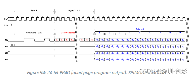
2.3 写入 LCD 数据
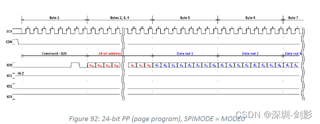
它使用 Opcode = 0x32 PP4O 来写入 LCD 数据。
static uint32_t gc9c01_bus_lcd_write_buffer(uint8_t *p_tx_buffer, uint32_t len, uint32_t addr)
{


        uint32_t err_code = 0;
        m_finished = false;
        err_code = nrf_drv_qspi_write(p_tx_buffer, len, addr);
        if(err_code != NRFX_SUCCESS)
        {


                // NRF_LOG_INFO("error code= 0x%x",err_code);
        }
        WAIT_FOR_PERIPH();
        return err_code;
}

static void BMP_picture_show(uint32_t delay, const uint16_t *p_data)
{


        uint32_t err_code;
        uint32_t * p_color;
        uint32_t i,k;
        uint32_t tran_size,now_size=0;
        uint32_t remain_size = GC9c01_DRV_ALL_SIZE;

        //NRF_LOG_INFO("%s block_dx = %d, Color=%04x", __func__, a block_dx, color);
        //static uint8_t __ALIGN(4) bank_buf[QSPI_PAG_SIZE];

        tran_size = QSPI_PAG_SIZE;
        memcpy(&m_buffer_tx[0], (uint8_t *)&p_data[0]+tran_size, tran_size);
        err_code = gc9c01_bus_lcd_write_buffer(m_buffer_tx, QSPI_PAG_SIZE, 0x002C00);

        remain_size -= tran_size;
        now_size=tran_size;
        while (remain_size)
        {


                if (remain_size > QSPI_PAG_SIZE)
                {


                        tran_size = QSPI_PAG_SIZE;
                }
                else
                {


                        tran_size = remain_size;
                }

                memcpy(m_buffer_tx, (uint8_t *)&p_data[0]+now_size, tran_size);

                now_size += tran_size;
                err_code = gc9c01_bus_lcd_write_buffer(&m_buffer_tx[0], tran_size, 0x003C00);

                remain_size -= tran_size;
        }

        nrf_delay_ms(delay);
}
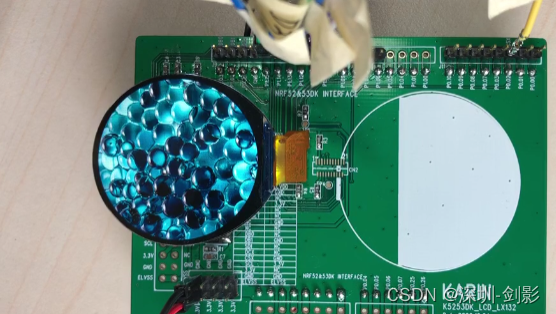
效果展示
参考链接访问地址