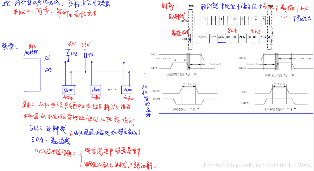
- IIC通信
#include "i2c_driver.h"
#include "systick_driver.h"
#define GPIO_PORT_I2C GPIOB /* GPIO端口 */
#define RCC_I2C_PORT RCC_APB2Periph_GPIOB /* GPIO端口时钟 */
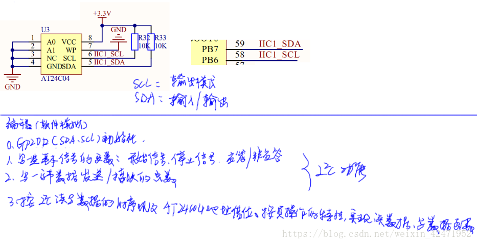
#define I2C_SCL_PIN GPIO_Pin_6 /* 连接到SCL时钟线的GPIO */
#define I2C_SDA_PIN GPIO_Pin_7 /* 连接到SDA数据线的GPIO */
#if 0 /* 条件编译: 1 选择GPIO的库函数实现IO读写 */
#define I2C_SCL_1() GPIO_SetBits(GPIO_PORT_I2C, I2C_SCL_PIN) /* SCL = 1 */
#define I2C_SCL_0() GPIO_ResetBits(GPIO_PORT_I2C, I2C_SCL_PIN) /* SCL = 0 */
#define I2C_SDA_1() GPIO_SetBits(GPIO_PORT_I2C, I2C_SDA_PIN) /* SDA = 1 */
#define I2C_SDA_0() GPIO_ResetBits(GPIO_PORT_I2C, I2C_SDA_PIN) /* SDA = 0 */
#define I2C_SDA_READ() GPIO_ReadInputDataBit(GPIO_PORT_I2C, I2C_SDA_PIN) /* 读SDA口线状态 */
#else /* 这个分支选择直接寄存器操作实现IO读写 */
/* 注意:如下写法,在IAR最高级别优化时,会被编译器错误优化 */
#define I2C_SCL_1() GPIO_PORT_I2C->BSRR = I2C_SCL_PIN /* SCL = 1 */
#define I2C_SCL_0() GPIO_PORT_I2C->BRR = I2C_SCL_PIN /* SCL = 0 */
#define I2C_SDA_1() GPIO_PORT_I2C->BSRR = I2C_SDA_PIN /* SDA = 1 */
#define I2C_SDA_0() GPIO_PORT_I2C->BRR = I2C_SDA_PIN /* SDA = 0 */
#define I2C_SDA_READ() ((GPIO_PORT_I2C->IDR & I2C_SDA_PIN) != 0) /* 读SDA口线状态 */
#endif
//GPIO初始化
void I2C_GPIOInitConfig(void)
{
GPIO_InitTypeDef GPIO_InitStructure;
RCC_APB2PeriphClockCmd(RCC_I2C_PORT,ENABLE);
GPIO_InitStructure.GPIO_Pin = I2C_SCL_PIN | I2C_SDA_PIN; //PB6 PB7
GPIO_InitStructure.GPIO_Speed = GPIO_Speed_50MHz;
GPIO_InitStructure.GPIO_Mode = GPIO_Mode_Out_PP; //推挽输出
GPIO_Init(GPIO_PORT_I2C, &GPIO_InitStructure);
GPIO_SetBits(GPIO_PORT_I2C, I2C_SCL_PIN | I2C_SDA_PIN); //设置初始电平为高电平
}
//SDA设置为输出模式
static void SDA_OUT(void)
{
GPIO_InitTypeDef GPIO_InitStructure;
GPIO_InitStructure.GPIO_Pin = I2C_SDA_PIN;
GPIO_InitStructure.GPIO_Speed = GPIO_Speed_50MHz;
GPIO_InitStructure.GPIO_Mode = GPIO_Mode_Out_PP;
GPIO_Init(GPIO_PORT_I2C, &GPIO_InitStructure);
GPIO_SetBits(GPIO_PORT_I2C,I2C_SDA_PIN);
}
//SDA输入模式
static void SDA_IN(void)
{
GPIO_InitTypeDef GPIO_InitStructure;
GPIO_InitStructure.GPIO_Pin = I2C_SDA_PIN;
GPIO_InitStructure.GPIO_Mode = GPIO_Mode_IPU;
GPIO_Init(GPIO_PORT_I2C, &GPIO_InitStructure);
// GPIO_SetBits(GPIO_PORT_I2C,I2C_SDA_PIN);
}
/**************************************
**************************************/
void I2C_Start()
{
SDA_OUT(); //设置SDA输出模式
I2C_SDA_1(); //将SDA设置为高电平
I2C_SCL_1(); //将SCL设置为高电平
delay_us(8);
I2C_SDA_0(); //将SDA设置为低电平
delay_us(8);
I2C_SCL_0(); //将SCL设置为低电平
}
/**************************************
**************************************/
void I2C_Stop()
{
SDA_OUT(); //设置SDA输出模式
I2C_SDA_0(); //将SDA设置为低电平
I2C_SCL_1(); //将SCL设置为高电平
delay_us(8);
I2C_SDA_1(); //将SDA设置为高电平
delay_us(8);
}
/**************************************
**************************************/
void I2C_SendACK(u8 ack)
{
SDA_OUT();
I2C_SCL_0();
delay_us(8);
if(ack)
I2C_SDA_1();
else I2C_SDA_0();
I2C_SCL_1();
delay_us(8);
I2C_SCL_0();
delay_us(8);
}
/**************************************
**************************************/
u8 I2C_RecvACK(void)
{
u8 ucErrTime=0;
SDA_IN(); //设置SDA输入模式
// I2C_SDA_1();
// delay_us(4);
I2C_SCL_1(); //将SCL设置为高电平
delay_us(4);
while(I2C_SDA_READ()) //检测SDA上是否出现低电平(ACK)
{
ucErrTime++;
if(ucErrTime>250) //超时间差
{
I2C_Stop(); //停止通信
return 1;
}
}
I2C_SCL_0(); //将SCL设置为低电平
return 0;
}
/**************************************
**************************************/
void I2C_SendByte(u8 dat)
{
u8 t;
SDA_OUT();
I2C_SCL_0();
for(t=0;t<8;t++)
{
// SDA=(dat&0x80)>>7;
if(dat&0x80)
I2C_SDA_1(); //将数据线上的电位设置好
else I2C_SDA_0();
dat<<=1;
delay_us(5);
I2C_SCL_1(); //时钟变化,数据发送出去
delay_us(5);
I2C_SCL_0();
delay_us(5);
}
// I2C_RecvACK();
}
/**************************************
**************************************/
u8 I2C_RecvByte(void)
{
int i = 0;
u8 byte = 0;
SDA_IN();
for(i = 0;i < 8;i++)
{
delay_us(5);
I2C_SCL_1(); //先接受一次数据线上的数据到寄存器
delay_us(5);
byte <<= 1;
if(I2C_SDA_READ()) //判断寄存器中的数据
{
byte |= 0x01;
}
I2C_SCL_0();
delay_us(5);
}
return byte;
}
/****************************************************************************
* 函 数 名: i2c_CheckDevice
* 功能说明: 检测I2C总线设备,CPU向发送设备地址,然后读取设备应答来判断该设备是否存在
* 形 参:_Address:设备的I2C总线地址
* 返 回 值: 返回值 0 表示正确, 返回1表示未探测到
****************************************************************************/
uint8_t I2C_CheckDevice(uint8_t _Address)
{
uint8_t ucAck;
I2C_Start(); /* 发送启动信号 */
/* 发送设备地址+读写控制bit(0 = w, 1 = r) bit7 先传 */
I2C_SendByte(_Address | I2C_WR);
ucAck = I2C_RecvACK(); /* 检测设备的ACK应答 */
I2C_Stop(); /* 发送停止信号 */
return ucAck;
}
- 用IIC通信实现EEPROM读写
#include "eeprom.h"
#include "i2c_driver.h"
#include "uart1_driver.h"
#include "systick_driver.h"
/*
*********************************************************************************************************
* 函 数 名: ee_CheckOk
* 功能说明: 判断串行EERPOM是否正常
* 形 参:无
* 返 回 值: 1 表示正常, 0 表示不正常
*********************************************************************************************************
*/
uint8_t eeprom_CheckOk(void)
{
if (I2C_CheckDevice(EE_DEV_ADDR) == 0)
{
return 1;
}
else
{
/* 失败后,切记发送I2C总线停止信号 */
I2C_Stop();
return 0;
}
}
/******************************************************************
* 函 数 名: eeprom_ReadBytes
* 功能说明: 从串行EEPROM指定地址处开始读取若干数据
* 形 参:_usAddress : 起始地址
* _usSize : 数据长度,单位为字节
* _pReadBuf : 存放读到的数据的缓冲区指针
* 返 回 值: 0 表示失败,1表示成功
********************************************************************/
uint8_t eeprom_ReadBytes(uint8_t *_pReadBuf, uint16_t _usAddress, uint16_t _usSize)
{
uint16_t i;
/* 采用串行EEPROM随即读取指令序列,连续读取若干字节 */
/* 第1步:发起I2C总线启动信号 */
I2C_Start();
/* 第2步:发起控制字节,高7bit是地址,bit0是读写控制位,0表示写,1表示读 */
// I2C_SendByte(EE_DEV_ADDR | I2C_WR); /* 此处是写指令 */
I2C_SendByte((0XA0|((_usAddress/256)<<1))|I2C_WR);
/* 第3步:发送ACK */
if (I2C_RecvACK() != 0)
{
goto cmd_fail; /* EEPROM器件无应答 */
}
/* 第4步:发送字节地址,24C02只有256字节,因此1个字节就够了,如果是24C04以上,那么此处需要连发多个地址 */
// I2C_SendByte((uint8_t)_usAddress);
I2C_SendByte((uint8_t)_usAddress%256);
/* 第5步:发送ACK */
if (I2C_RecvACK() != 0)
{
goto cmd_fail; /* EEPROM器件无应答 */
}
/* 第6步:重新启动I2C总线。前面的代码的目的向EEPROM传送地址,下面开始读取数据 */
I2C_Start();
/* 第7步:发起控制字节,高7bit是地址,bit0是读写控制位,0表示写,1表示读 */
// I2C_SendByte(EE_DEV_ADDR | I2C_RD); /* 此处是读指令 */
I2C_SendByte((0XA0|((_usAddress/256)<<1))|I2C_RD);
/* 第8步:发送ACK */
if (I2C_RecvACK() != 0)
{
goto cmd_fail; /* EEPROM器件无应答 */
}
/* 第9步:循环读取数据 */
for (i = 0; i < _usSize; i++)
{
_pReadBuf[i] = I2C_RecvByte(); /* 读1个字节 */
/* 每读完1个字节后,需要发送Ack, 最后一个字节不需要Ack,发Nack */
if (i != _usSize - 1)
{
I2C_SendACK(0); /* 中间字节读完后,CPU产生ACK信号(驱动SDA = 0) */
}
else
{
I2C_SendACK(1); /* 最后1个字节读完后,CPU产生NACK信号(驱动SDA = 1) */
}
}
/* 发送I2C总线停止信号 */
I2C_Stop();
return 1; /* 执行成功 */
cmd_fail: /* 命令执行失败后,切记发送停止信号,避免影响I2C总线上其他设备 */
/* 发送I2C总线停止信号 */
I2C_Stop();
printf("Read fild!\r\n");
return 0;
}
/**********************************************************************************
* 函 数 名: eeprom_WriteBytes
* 功能说明: 向串行EEPROM指定地址写入若干数据,采用页写操作提高写入效率
* 形 参:_usAddress : 起始地址
* _usSize : 数据长度,单位为字节
* _pWriteBuf : 存放读到的数据的缓冲区指针
* 返 回 值: 0 表示失败,1表示成功
**********************************************************************************/
uint8_t eeprom_WriteBytes(uint8_t *_pWriteBuf, uint16_t _usAddress, uint16_t _usSize)
{
uint16_t i,m;
uint16_t usAddr;
/*
写串行EEPROM不像读操作可以连续读取很多字节,每次写操作只能在同一个page。
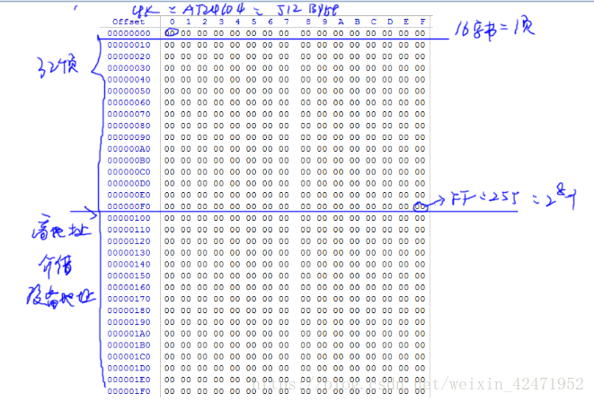
对于24xx04,page size = 16
简单的处理方法为:按字节写操作模式,没写1个字节,都发送地址
为了提高连续写的效率: 本函数采用page wirte操作。
*/
usAddr = _usAddress;
for (i = 0; i < _usSize; i++)
{
/* 当发送第1个字节或是页面首地址时,需要重新发起启动信号和地址 */
if ((i == 0) || (usAddr & (EE_PAGE_SIZE - 1)) == 0)
{
/* 第0步:发停止信号,启动内部写操作 */
I2C_Stop();
/* 通过检查器件应答的方式,判断内部写操作是否完成, 一般小于 10ms
CLK频率为200KHz时,查询次数为30次左右
*/
for (m = 0; m < 100; m++)
{
/* 第1步:发起I2C总线启动信号 */
I2C_Start();
/* 第2步:发起控制字节,高7bit是地址,bit0是读写控制位,0表示写,1表示读 */
// I2C_SendByte(EE_DEV_ADDR | I2C_WR); /* 此处是写指令 */
I2C_SendByte((0XA0|((usAddr/256)<<1))|I2C_WR);
/* 第3步:发送一个时钟,判断器件是否正确应答 */
if (I2C_RecvACK() == 0)
{
break;
}
}
// if (m == 1000)
// {
// goto cmd_fail; /* EEPROM器件写超时 */
// }
/* 第4步:发送字节地址,24C02只有256字节,1个字节就够了,如果是24C04以上,那么此处需要连发多个地址 */
I2C_SendByte((uint8_t)usAddr%256);
// I2C_SendByte((uint8_t)usAddr/256);
// I2C_SendByte((uint8_t)usAddr);
/* 第5步:发送ACK */
if (I2C_RecvACK() != 0)
{
goto cmd_fail; /* EEPROM器件无应答 */
}
}
/* 第6步:开始写入数据 */
I2C_SendByte(_pWriteBuf[i]);
/* 第7步:发送ACK */
if (I2C_RecvACK() != 0)
{
goto cmd_fail; /* EEPROM器件无应答 */
}
usAddr++; /* 地址增1 */
}
/* 命令执行成功,发送I2C总线停止信号 */
I2C_Stop();
return 1;
cmd_fail: /* 命令执行失败后,切记发送停止信号,避免影响I2C总线上其他设备 */
/* 发送I2C总线停止信号 */
I2C_Stop();
printf("Write fild!\r\n");
return 0;
}
void eeprom_Erase(void)
{
uint16_t i;
uint8_t buf[EE_SIZE];
/* 填充缓冲区 */
for (i = 0; i < EE_SIZE; i++)
{
buf[i] = 0xff;
}
/* 写EEPROM, 起始地址 = 0,数据长度为 512 */
if (eeprom_WriteBytes(buf, 0, EE_SIZE) == 0)
{
printf("Erase eeprom error\r\n");
return;
}
else
{
printf("Erase eeprom Success\r\n");
}
}
uint8_t write_buf[EE_SIZE];
uint8_t read_buf[EE_SIZE];
/*
* eeprom AT24C02 读写测试
*/
void eeprom_Test(void)
{
uint16_t i;
if(eeprom_CheckOk() == 0)
{
/* 没有检测到EEPROM */
printf("Not check EEPROM!\r\n");
while (1); /* 停机 */
}
/* 填充测试缓冲区 */
for (i = 0; i < EE_SIZE/2; i++)
{
write_buf[i] = i;
}
for (i = 0; i < EE_SIZE/2; i++)
{
write_buf[256+i] = i;
}
if (eeprom_WriteBytes(write_buf, 0, EE_SIZE) == 0)
{
printf("Write eeprom error\r\n");
return;
}
else
{
printf("Write eeprom Success!\r\n");
}
// eeprom_Erase();
/*写完之后需要适当的延时再去读,不然会出错*/
delay_ms(20);
/*-----------------------------------------------------------------------------------*/
if (eeprom_ReadBytes(read_buf, 0, EE_SIZE) == 0)
{
printf("Read eeprom error\r\n");
return;
}
else
{
printf("Read eeprom Success\r\n");
}
for (i = 0; i < EE_SIZE; i++)
{
printf(" %02X", read_buf[i]);
if ((i & 15) == 15)
{
printf("\r\n");
}
}
}
头文件
#ifndef _EEPROM_H_
#define _EEPROM_H_
#include "stm32f10x.h"
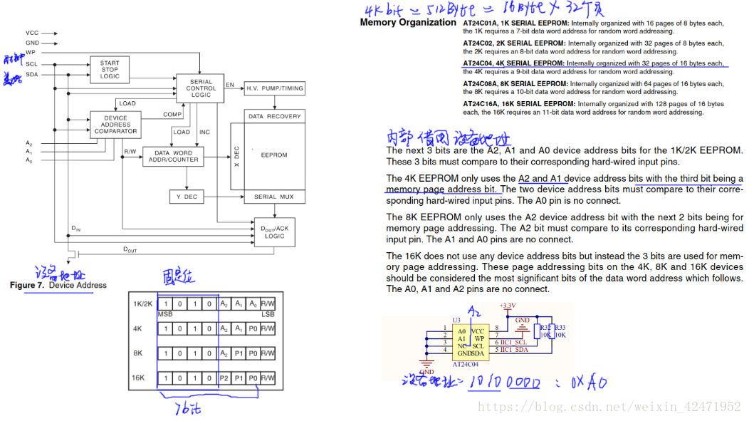
#define EE_DEV_ADDR 0xA0 /* 24xx04的设备地址 */
#define EE_PAGE_SIZE 16 /* 24xx04的页面大小 */
#define EE_SIZE 512 /* 24xx04总容量 */
uint8_t eeprom_CheckOk(void);
uint8_t eeprom_ReadBytes(uint8_t *_pReadBuf, uint16_t _usAddress, uint16_t _usSize);
uint8_t eeprom_WriteBytes(uint8_t *_pWriteBuf, uint16_t _usAddress, uint16_t _usSize);
void eeprom_Erase(void);
void eeprom_Test(void);
#endif
#ifndef _I2C_DRIVER_H_
#define _I2C_DRIVER_H_

#include "stm32f10x.h"
#include <inttypes.h>

#define I2C_WR	0		/* 写控制bit */
#define I2C_RD	1		/* 读控制bit */


void I2C_GPIOInitConfig(void);
void I2C_Start(void);
void I2C_Stop(void);
void I2C_SendACK(u8 ack);
u8 I2C_RecvACK(void);

void I2C_SendByte(u8 dat);
u8 I2C_RecvByte(void);


uint8_t I2C_CheckDevice(uint8_t _Address);

#endif