部分转载自:http://www.firewall.cx/networking-topics/general-networking/107-network-multicast.html
剩下的基本参考谢希仁计算机网络7th
1. 基本概念
IP多播直观上可以按照下图理解,源主机只需要发送一份数据,而网络中的路由器在转发该数据时需要将它复制多份,分别发给在该个多播组内的所有主机。也就是说,IP多播必须依赖于多播路由器,这些路由器具有识别多播包的功能,当然,多播路由器也能转发单播包。
我们知道,ip网络中每个主机都有自己唯一的IP地址(为简化问题,这里忽略NAT,只考虑公共IP),那如何让一个多播数据包到达该多播组内的多台主机呢?肯定不能将这么多主机的ip地址都写入该多播数据包的目的ip包头域(长度限制),而是在该多播数据包的目的ip地址域中写入D类地址(224.0.0.0—239.225.225.225 前4bit固定为1110),每个D类地址对应一个多播组,则D类地址可以标志2^28个多播组。因此,多播数据包与一般的单播广播数据包的区别是它的目的ip地址为D类地址,并且ip首部中的协议字段为2,表明采用的是IGMP网际组管理协议。(需要注意的是多播数据包的目的ip地址实际上不可能对应某一台真实存在的主机的ip地址,也就是说该目的ip地址永远不可能作为源地址,即多播ip地址只能用于目的ip地址,不能用于源ip地址)
ip多播可以分为两种,一种是在本地局域网上进行硬件多播,第二种是在互联网的范围内进行多播。第二种最后还是需要依赖于把多播数据包在局域网上用硬件多播交付给多播组的所有成员。
2. 硬件多播
关于硬件多播,这篇文章讲得很好:http://www.firewall.cx/networking-topics/general-networking/107-network-multicast.html
A multicast is similar to a broadcast in the sense that its target is a number of machines on a network, but not all. Where a broadcast is directed to all hosts on the network, a multicast is directed to a group of hosts. The hosts can choose whether they wish to participate in the multicast group (often done with the Internet Group Management Protocol), whereas in a broadcast, all hosts are part of the broadcast group whether they like it or not!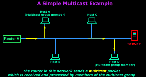
As you are aware, each host on an Ethernet network has a unique MAC address, so here's the million dollar question: How do you talk to a group of hosts (our multicast group), where each host has a different MAC address, and at the same time ensure that the other hosts, which are not part of the multicast group, don't process the information ? You will soon know exactly how all this works.(解释一下标红:现在局域网大部分采用的都是以太网标准,共享信道)
To keep things in perspective and make it easy to understand, we are going to concentrate only on an Ethernet network using the IP protocol, which is what 80-90 % of home networks and offices use.
BREAKING THINGS DOWN...
In order to explain Multicasting the best I can and to make it easier for you understand, I decided to break it down into 3 sections:
1) Hardware/Ethernet Multicasting
2) IP Multicasting
3) Mapping IP Multicast to Ethernet Multicast
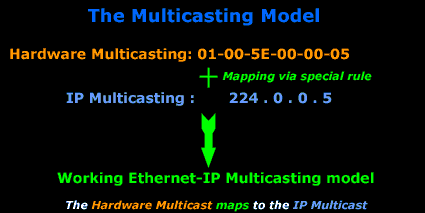
A typical multicast on an Ethernet network, using the TCP/IP protocol, consists of two parts: Hardware/Ethernet multicast and IP Multicast. Later on I will talk about Mapping IP Multicast to Ethernet Multicast which is really what happens with multicasting on our Ethernet network using the TCP/IP protocol.
The brief diagram below shows you the relationship between the 3 and how they complete the multicasting model:
HARDWARE/ETHERNET MULTICASTING
When a computer joins a multicast group, it needs to be able to distinguish between normal unicasts (which are packets directed to one computer or one MAC address) and multicasts. With hardware multicasting, the network card is configured, via its drivers, to watch out for particular MAC addresses (in this case, multicast MAC addresses) apart from its own. When the network card picks up a packet which has a destination MAC that matches any of the multicast MAC addresses, it will pass it to the upper layers for further processing.(说一下自己的理解:网卡不仅有自己的mac地址,还会关注自己加入的多播组的ip地址对应的mac地址,比如该主机加入了多播组224.128.64.32,那么这个主机的网卡就会额外关注MAC地址为01-00-5E-00-40-20的多播包,但是同时由于多播ip地址与多播mac地址不是一一对应的关系(下文会说多播ip与多播mac的对应关系以及多播mac怎么取值),因此mac地址为01-00-5E-00-40-20的多播包不一定就会对应224.128.64.32,比如他也可以对应多播组224.0.64.32,因此网卡收到mac地址为01-00-5E-00-40-20的多播包时,还需要将这个包扔给上层去处理,ip层利用软件过滤,丢弃不是发给自己的多播包)
And this is how they do it:
Ethernet uses the low-order bit of the high-order octet to distinguish conventional unicast addresses from multicast addresses. A unicast would have this bit set to ZERO (0), whereas a multicast would be set to ONE (1)
插播一句:这里是说,以太网硬件地址字段中的第一个字节的最低位为1即为多播地址,且这种多播地址占IANA(互联网号码指派管理局)分配到的地址数的一半。由于IANA拥有的以太网地址块的为00-00-5E-00-00-00到00-00-5E-FF-FF-FF,则以太网硬件多播地址范围为01-00-5E-00-00-00到01-00-5E-7F-FF-FF
To understand this, we need to analyse the destination MAC address of a unicast and multicast packet, so you can see what we are talking about:
When a normal (unicast) packet is put on the network by a computer, it contains the Source and Destination MAC address, found in the 2nd Layer of the OSI model. The following picture is an example of my workstation (192.168.0.6) sending a packet to my network's gateway (192.168.0.5):
Now let's analyse the destination MAC address: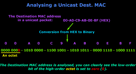
When my gateway receives the packet, it knows it's a unicast packet as explained in the above picture.
Let's now have a look at the MAC address of a multicast packet. Keep in mind, a multicast packet is not directed to one host but a number of hosts, so the destination MAC address will not match the unique MAC address of any computer, but the computers which are part of the multicast group will recognise the destination MAC address and accept it for processing.
The following multicast packet was sent from my NetWare server. Notice the destination MAC address (it's a multicast):

Analysis of a multicast destination MAC address: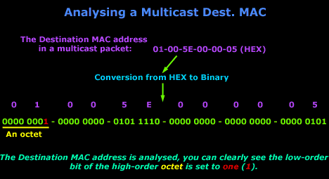
So now you should be able to understand how computers can differentiate between a normal or unicast packet and a multicast packet. Again, the destination MAC address 01-00-5E-00-00-05 is not the MAC address of a particular host-computer but the MAC address that can be recognised by computers that are part of the multicast group. I should also note that you will never find a source address that is a multicast MAC address, the source address will always be a real one, to identify which computer the packet came from.
The IEEE group used a special Rule to determine the various MAC addresses that will be considered for multicasting. This Rule is covered in the last section of this page, but you don't need to know it now in order to understand Hardware multicasting. Using this special rule it was determined that MAC address 01:00:5E:00:00:05 will be used for the OSPF protocol, which happens to be a routing protocol, and then this MAC address also maps to an IP address which is analysed in IP Multicast.
IP MULTICAST
The IP Multicast is the second part of multicasting which, combined with the hardware multicasting, gives us a multicasting model that works for our Ethernet network. If hardware multicasting fails to work, then the packet will never arrive at the network layer upon which IP multicasting is based, so the whole model fails.
With IP multicasting the hardware multicasting MAC address is mapped to an IP Address. Once Layer 2 (Datalink) picks the multicast packet from the network (because it recognises it, as the destination MAC address is a multicast) it will strip the MAC addresses off and send the rest to the above layer, which is the Network Layer. At that point, the Network Layer needs to be able to understand it's dealing with a multicast, so the IP address is set in a way that allows the computer to see it as a multicast datagram. A host may send multicast datagrams to a multicast group without being a member.
Multicasts are used a lot between routers so they can discover each other on an IP network. For example, an Open Shortest Path First (OSPF) router sends a "hello" packet to other OSPF routers on the network. The OSPF router must send this "hello" packet to an assigned multicast address, which is 224.0.0.5, and the other routers will respond.
IP Multicast uses Class D IP Adresses: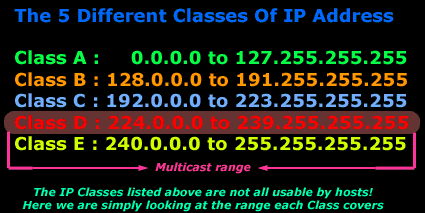
Let's have a look at an example so we can understand that a bit better:
The picture below is a screenshot from my packet sniffer, it shows a multicast packet which was sent from my NetWare server, notice the destination IP address:

The screenshot above shows the packet which was captured, it's simply displaying a quick summary of what was caught. But, when we look on the left, we see the above packet in much more detail.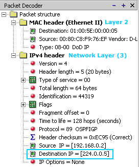
You can clearly see the markings I have put at the bottom which show you that the destination IP for this packet is IP Address 224.0.0.5. This corresponds to a multicast IP and therefore is a multicast packet.
The MAC header also shows a destination MAC address of 01-00-5E-00-00-05 which we analysed in the previous section to show you how this is identified as a multicast packet at Layer 2 (Datalink Layer).
Some examples of IP multicast addresses:
224.0.0.0 Base Address (Reserved) [RFC1112,JBP]
224.0.0.1 All Systems on this Subnet [RFC1112,JBP]
224.0.0.2 All Routers on this Subnet [JBP]
224.0.0.3 Unassigned [JBP]
224.0.0.4 DVMRP Routers [RFC1075,JBP]
224.0.0.5 OSPFIGP OSPFIGP All Routers [RFC2328,JXM1]
Remember that these IP Addresses have been assigned by the IEEE !
Now all that's left is to explain how the IP multicast and MAC multicast map between each other...
MAPPING IP MULTICAST TO ETHERNET MULTICAST
The last part of multicast which combines the Hardware Multicasting and IP Multicasting is the Mapping between them. There is a rule for the mapping, and this is it:
To map an IP Multicast address to the corresponding Hardward/Ethernet multicast address, place the low-order 23 bits of the IP multicast address into the low-order 23 bits of the special Ethernet multicast address. The rest of the high-order bits are defined by the IEEE (yellow colour in the example)
插播一下:这里说的是如何根据多播数据包的目的ip地址(比如223.0.0.5)决定它的目的MAC地址(应该是01-00-5E-00-00-05),之所以只能映射低23位ip到低23位mac是因为之前说过,多播mac地址块只有低23bit可变,但是多播ip地址可以有28bit可变,这就导致会有多个ip多播地址映射到一个多播mac地址,因此网卡收到多播数据包时,还需要给ip层看看是不是给自己的(软件过滤)。
The above rule basically determines the Hardware MAC address. Let's have a look at a real example to understand this.
We are going to use Multicast IP Address 224.0.0.5 - a multicast for the OSPF routing protocol. The picture below shows us the analysis of the IP address in binary so we can clearly see all the bits:
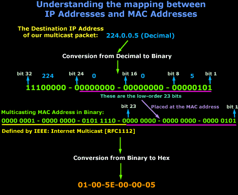
It might seem a bit confusing at first, but let's break it down:
We have an IP Address of 224.0.0.5, this is then converted into binary so we can clearly see the mapping of the 23 bits to the MAC address of the computer. The MAC Address part which is in yellow has been defined by the IEEE group. So the yellow and pink line make the one MAC Address as shown in binary mode, then we convert it from binary to hex and that's about it !
3. 互联网范围多播
IP多播需要两种协议:IGMP网际组管理协议以及多播路由选择协议。
3.1 IGMP协议
IGMP协议是让连接在本地局域网上的多播路由器知道本局域网上是否有主机(严格讲,是主机的某个进程)参加或者退出了某个多播组。IGMP协议具体的工作过程这里不再叙述,可以参见谢希仁的书。强调,多播数据包的发送者和接受者都知道一个多播组的成员有多少,也不知道这些成员分别对应哪些主机。任何应用进程都可以在任何时候向任何一个多播组发送多播数据包,而且该应用程序并不需要加入这个多播组。
3.2. 多播路由选择协议
仅有IGMP是不能完成多播任务的,连接在局域网上的多播路由器还必须和互联网上其他的多播路由器协同工作,以便把多播数据包用最小的代价传送给所有的组成员,这就需要使用多播路由选择协议。多播路由选择协议并未被标准化,多播路由选择实际上就是要找出以源主机为根节点的多播转发树,它们在转发数据包时使用了以下的三种方法(均来自谢希仁的书....不想手打...太懒了...):


