首先需要了解uart 的通信协议和传输时序
uart通信首先将接收到的并行数据转换成串行数据来传输。消息帧起始位为低电平,后面接7或8个数据位(大部分为8个数据位),1个可用的奇偶校验位(根据数据中1的个数是否为偶数(偶校验位)还是奇数(奇校验位)),1个或者多个高位停止位。(传输一个字节大约需要10个比特位)
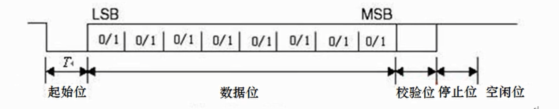
(T为一个数据位占用的时间,如果波特率为9600,那么T4=1/9600)
实验实现,当按键key1按下,不断发送一个常数,在串口调试助手上可以查看。利用状态机实现
module uart_tx(
input clk, //时钟输入
input rst_n, //复位输入
input key, //一个按键,用于发送控制,低电平有效
output reg txd //串口发送管脚
);
//状态机状态定义,空闲位+开始位+8bit数据位+停止位
parameter S_IDLE = 4'd0; //空闲状态
parameter S_START = 4'd1; //发送1BIT起始码0
parameter S_BIT0 = 4'd2; //发送第一位数据
parameter S_BIT1 = 4'd3;
parameter S_BIT2 = 4'd4;
parameter S_BIT3 = 4'd5;
parameter S_BIT4 = 4'd6;
parameter S_BIT5 = 4'd7;
parameter S_BIT6 = 4'd8;
parameter S_BIT7 = 4'd9;
parameter S_STOP = 4'd10;//发送停止位 1
reg [3:0] state; //定义状态寄存器,11个状态,2^4=16,足够
reg[15:0] bit_timer; //用于控制波特率的计数器如果波特率是9600,每个数据位50000000/9600个时钟周期
wire[7:0] tx_data; //发送的固定数据12
assign tx_data = 8'hAB; //此处可以修改发送的数据
//----------一段式状态机编写
always@ (posedge clk or negedge rst_n)
begin
if (!rst_n)
begin
state<=S_IDLE;
bit_timer<=16'd0;
txd<=1'b1; //复位发送管脚为高电平,因为开始为低电平
end
else
begin
case(state)
S_IDLE:
begin
txd<=1'b1;
bit_timer <= 16'd0;
if(!key) //如果按键按下
state<=S_START;
else
state<=state;
end
S_START:
begin
txd<=1'b0; //开始状态
if(bit_timer == 16'd5208)//一个BIT的时间到了,状态转换
begin
state <= S_BIT0;
bit_timer <= 16'd0;
end
else
begin
state <= state;
bit_timer <=bit_timer+16'd1;
end
end
S_BIT1:
begin
txd <= tx_data[1]; //第二位数据
if(bit_timer == 16'd5208)
begin
state <= S_BIT2;
bit_timer <= 16'd0;
end
else
begin
state <= state;
bit_timer <= bit_timer + 16'd1;
end
end
S_BIT2:
begin
txd <= tx_data[2]; //第三位数据
if(bit_timer == 16'd5208)
begin
state <= S_BIT3;
bit_timer <= 16'd0;
end
else
begin
state <= state;
bit_timer <= bit_timer + 16'd1;
end
end
S_BIT3:
begin
txd <= tx_data[3]; //第四位数据
if(bit_timer == 16'd5208)
begin
state <= S_BIT4;
bit_timer <= 16'd0;
end
else
begin
state <= state;
bit_timer <= bit_timer + 16'd1;
end
end
S_BIT4:
begin
txd <= tx_data[4]; //第五位数据
if(bit_timer == 16'd5208)
begin
state <= S_BIT5;
bit_timer <= 16'd0;
end
else
begin
state <= state;
bit_timer <= bit_timer + 16'd1;
end
end
S_BIT5:
begin
txd <= tx_data[5]; //第六位数据
if(bit_timer == 16'd5208)
begin
state <= S_BIT6;
bit_timer <= 16'd0;
end
else
begin
state <= state;
bit_timer <= bit_timer + 16'd1;
end
end
S_BIT6:
begin
txd <= tx_data[6]; //第七位数据
if(bit_timer == 16'd5208)
begin
state <= S_BIT7;
bit_timer <= 16'd0;
end
else
begin
state <= state;
bit_timer <= bit_timer + 16'd1;
end
end
S_BIT7:
begin
txd <= tx_data[7];//最后一位数据
if(bit_timer == 16'd5208)
begin
state <= S_STOP;
bit_timer <= 16'd0;
end
else
begin
state <= state;
bit_timer <= bit_timer + 16'd1;
end
end
S_STOP:
begin
txd <= 1'b1;//停止位为高电平
if(bit_timer == 16'd5208)
begin
state <= S_IDLE;
bit_timer <= 16'd0;
end
else
begin
state <= state;
bit_timer <= bit_timer + 16'd1;
end
end
default:
begin
state <= S_IDLE;
end
endcase
end
end