In this lab, basics of bipolar stepper motors are provided. ThePmodSTEP – by Digilent is used as a sister-board to electrically drive a stepper motor (bipolar, 1.8 degree/step, 0.33A, 12V). The sister-board is connected through the Pmod connector (JA1)of Zedboard. The necessary external connections and physical constraints needed to connect an external component to Zedboard are outlined and explained. An application is developed to control the motor direction and speed through the push buttons on Zedboard.

Design Flow-Lab9

Block Diagram-Lab9

Board Interface-Lab9
Background Information
A-Stepper Motor
Stepper motors are widely used in applications that require precise positioning (e.g. robotics, disk drives, printers, etc…). A stepper motor uses a magnetized rotor and four electromagnets in its stator (the motor casing). Depending on the polarity of the magnetic fields generated when the electromagnet coils are energized, a magnetic force acts upon the magnetic teeth of the rotor and cause it to turn. To keep the rotor turning, the electromagetics should be magnetized in a specific sequence of step signals.The steps signals are typically generated by an embedded system. The sequence can be used to turn the rotor clockwise or counter-clockwise. The coils can be energized one at a time, or two at a time to generate more torque(two coils at a time method is used in this lab). In our system an application running on the ARM processor keeps checking the push buttons and generates specific sequences(depending on the push button being pressed) and send it to through a GPIO to the motor drive board(PmodSTEP) connected to the JA1 Pmood connector.


Stepper Motor Rotating CW Triggering Sequence
Stepper motors come in different sizes and specifications. They differ in the maximum torque generated, gearing, rated voltage and current, number of phases, wiring and most importunately the resolution (aka: precision, aka: degrees per step),which is how many angular degrees per one step of the motor,sometimes its given as step count (how many steps per complete revolution). Commercially available stepper motors have step counts of 24, 48 and 200. A stepper motor of 1.8 degree resolution could be also named as a 200 step/revolution motor.

Different Types of Stepper Motors
The stepper motor used in this lab is SM-42BYG011-25 by Mercury Motor its a simple yet very powerful bipolar (2 phases) stepper motor with a 4-wire cable attached.

SM-42BYG011-25 Stepper Motor

SM-42BYG011-25 Wiring Diagram
The specifications of this motor is as below:
- Resolution (degrees) : 1.8
- Phases : 2
- Rated Voltage : 12V
- Rated Current : 0.33A
- Holding Torque : 2.3kg*cm
- Diameter Drive Shaft: 5mm
- Winding resistance: 32.6 Ω
- Total inertia (kg.m.m): 3.5 Kg.m.m
- Total friction (kg.m/s): 4 Kg.m/s
- Motor Width: 42mm (1.67”)
The motor is rotated by energizing adjacent coils in the same polarity simultaneously.

Energizing Sequence
Four core functions are implemented in the application running on the ARM:
Function step_cw() makes the motor rotates 7.2 degrees (4×1.8) clockwise. It uses the exact same energizing sequence shown in the picture above.
Function step_ccw() makes the motor rotates 7.2 degrees (4×1.8) counter clockwise. It simply go through the energizing sequence in the opposite direction.

step_cw and step_ccw functions
These two functions use the GPIO write function(XGpio_DiscreteWrite) to send signals to the PmodSTEP drive board connected on the JA1 Pmod connector. The delay period controls the speed of rotation. By changing the #define SPEED used in the delay function you can change the speed of the motor.
Functions rotate360_cw() and rotate360_ccw(). As the name implies, they rotate 360 degrees clockwise and counter clockwise respectively. Internally they call the step_cw()/ step_ccw() fifty times(50×7.2=360).

rotate360_cw() and rotate360_ccw() functions
B-PmodSTEP ( Stepper motor drive board)
The stepper motor consumes relatively higher power than the Zedboard can offer. Therefore, the motor needs to be powered externally using a drive circuit. The PmodStep by Digilent is designed to provide an easy means to drive a stepper motor. It connects to a host board using an 12-pin Pmod connector. It contains a four channel power amplifier, capable of driving up to 600 mA of current per channel, which is more than enough for our 330 mA motor. The PmodStep has eight digital I/O signals on header J1, all of which are connected to indication LEDs to show the current states of the signals. Only four signals were used here: JA7, JA8, JA9, JA10 their LEDs are: LEDH , LEDG ,LEDF ,LEDE . The PmodStep is powered externally from a 12V DC power supply using the external power screw terminal block.

PmodSTEP – Stepper Motor Drive Board

PmodSTEP Simplified Wiring Diagram
Objectives
1.Learn the basics of stepper motors structure and control.
2.Review the PmodSTEP drive board and understand its functuionality.
3.Practice attaching external components to the Zedboard.
Procedures
A-Create a project in Vivado to target the Zedboard
Follow the same five steps in Procedures-A of Lab1. However, in step3 name your project “lab9”.
B-Create an embedded processor project using the IP Integrator
Follow the same four steps in Procedures-B of Lab1.
C- Configure the ZYNQ7 Processing System
Follow the same five steps in Procedures-C of Lab1.
D-Add GPIO for Stepper Motor
This is the GPIO that will be linked to the JA1 Pmod connector on the Zedboard. Specifically to signals JA7-JA10.

JA1 Pmod Connector- Zedboard
1.Click on Add IP wizard![]() . The IP catalog window will appear showing you all IPs that can be added in this design. Type the name ” gpio” in the search field. double-click AXI GPIO to add it.
. The IP catalog window will appear showing you all IPs that can be added in this design. Type the name ” gpio” in the search field. double-click AXI GPIO to add it.

Block diagram after adding GPIO
2.Double click on axi_gpio_0 to configure it. In the IP Configuration tab, select All Outputs and set the GPIO Width to 4. Click OK to exit the Re-customize IP window.

Configure axi_gpio_0
3.Hove the mouse over GPIO port until it changes to a pencil shape. Right click and select Make External. The block diagram should look like the figure below.

Block diagram after Configuring GPIO
E-Add GPIO for Push Buttons
1.Click on Add IP wizard![]() again . The IP catalog window will appear showing you all IPs that can be added in this design. Type the name ” gpio” in the search field. double-click AXI GPIO to add it.
again . The IP catalog window will appear showing you all IPs that can be added in this design. Type the name ” gpio” in the search field. double-click AXI GPIO to add it.
2.Notice that Designer Assistance is available in the upper left side of the diagram view. Click on Run Connection Automation. The Run Connection Automation window will pop up, select All Automation (3 out of 3 selected)

Run Connection Automation(3 out of 3 selected)
Make sure that all the S_AXI Clock Connections are set to the default value of Auto, and GPIO for axi_gpio_1 is set to btns_5bits , just to stay on the safe side.

Run Connection Automation(S_AXI- axi_gpio_0)

Run Connection Automation(S_AXI- axi_gpio_1)

Run Connection Automation(GPIO- axi_gpio_1)
3.Right click on a free location in the diagram view and select Regenerate layout ![]() . The block diagram should be similar to the one below:
. The block diagram should be similar to the one below:

Block diagram after adding and configuring two GPIOs
F-Add physical constraints
1.In the Flow Navigator window, select Add Sources from the Project Manager section.

Add Sources
2.The Add Sources dialogue will open. Select Add or Create Constraints.

Add or Create constraints
3.Click Next, then click on the green + symbol and select Create File

Create a new constraint file
In the next window, Select XDC as the File type and enter stepper_motor as the File name

Name new constraints file : stepper_motor
Click OK, then click Finish in the next window to create the file and close the dialogue. In the Sources tab, expand the Constraints group and open the newly createdXDC file by double clicking on stepper_motor.xdc

Sources pane with stepper_motor selected
Add the following lines to the constraints file, alternatively, it can be copied from the constraints file stepper_motor.xdc available on a my GitHub page.
set_property PACKAGE_PIN AA8 [get_ports {gpio_tri_o[3]}]
set_property PACKAGE_PIN AB9 [get_ports {gpio_tri_o[2]}]
set_property PACKAGE_PIN AB11 [get_ports {gpio_tri_o[0]}]
set_property PACKAGE_PIN AB10 [get_ports {gpio_tri_o[1]}]
set_property IOSTANDARD LVCMOS33 [get_ports {gpio_tri_o[3]}]
set_property IOSTANDARD LVCMOS33 [get_ports {gpio_tri_o[2]}]
set_property IOSTANDARD LVCMOS33 [get_ports {gpio_tri_o[1]}]
set_property IOSTANDARD LVCMOS33 [get_ports {gpio_tri_o[0]}]
Click Save ![]() . The physical constraints here connect the GPIO ports to the pins on the chip connected to JA7, JA8, JA9, JA10 of JA1 Pmond connector on Zedboard.
. The physical constraints here connect the GPIO ports to the pins on the chip connected to JA7, JA8, JA9, JA10 of JA1 Pmond connector on Zedboard.
G-Generate Bitstream
1.In the Sources pane, Right click on system.bd and select Create HDL Wrapper to create the top level Verilog file from the block diagram. Select Let Vivado manage wrapper and auto-update when prompted with the next message. Notice that system_wrapper.v got created and placed at the top of the design sources hierarchy.

Create HDL Wrapper
2.In the Program and Debug section in the Flow Navigator pane, click Generate Bitstream. A dialog box will appear to ask you to save the modification you made, click Save.

Generating Bitstream
Generating the Bitstream may take a while to complete, depending on the performance of your machine. After the bitstream generation completes select View Reports in the dialog box, and click OK.
H-Export hardware design to SDK
1.Click File > Export > Export Hardware, make sure you select Include bitstream.
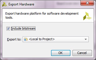
Export Hardware to SDK
2.Select File>Launch SDK. This will open up SDK, notice that all the files related to design including the IPs have now been exported to SDK.
I-Working with SDK
1.In SDK, select File > New > Application Project.
2.In the next window, enter the parameters as provided in the snapshot below:

New Standalone C Project – stepper_test
In the next window, select Empty Application from the available templates and click Finish. This will compile the BSP and the related drivers.
3.Expand stepper_test project directory, right click on src directory, New->Source File.

New C Source File – lab9.c
4.In the next window that shows up type “lab9.c” in the Source file and click Finish. This will create an empty C file in the src directory.

lab9.c empty source file created in SDK
5.Paste the content of lab9.c ( Available on my Github page) in in the editor view of lab9.c of SDK. Click on Save ![]() or hit (Ctrl+S) , by doing so both lab9 application, and its BSP are compiled automatically and the executable .elf file is generated(the default settings of SDK triggers compilation with Save). This is the executable file that the ARM processor on the PS side of the Zynq will execute.
or hit (Ctrl+S) , by doing so both lab9 application, and its BSP are compiled automatically and the executable .elf file is generated(the default settings of SDK triggers compilation with Save). This is the executable file that the ARM processor on the PS side of the Zynq will execute.
J-Download Bitstream and Run Application ( Hardware Verification )
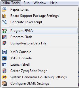
1.Select Xilinx Tools-> Program FPGA to download the Bitstream (this will take few seconds).
2.Select stepper_test project directory-> Run As-> Launch on Hardware (GDB) to run stepper_test application on the ARM processor.

Run application on ARM processor
Make sure that STEPmod connections is exactly like the figure below: Use the header Pmod 12-pin cable to connect Zedboard with STEPmod (this cables comes with the STEPmod, you just need to attach the male-male converter from the Zedboard side). As for the motor, you might need to buy a header in case its not shipped with it.

STEPmod Connections

Pmod Cable -12 pin
Now you can control the motor as follows :
Push Button Right: Rotate clockwise 7.2 degrees
Push Button Left: Rotate counter clockwise 7.2 degrees
Push Button Up: Rotate clockwise 360 degrees
Push Button Down: Rotate counter clockwise 360 degrees
By this you have completed Lab9 -Stepper Motor Controller. You can find the complete solution of this lab in here.