STM32F0的低功耗模式
详细内容见参考手册—Power control (PWR)
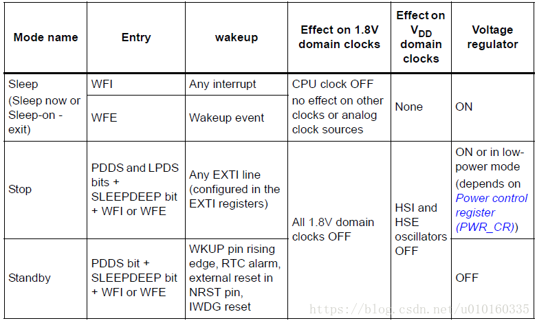
在STM32应用中,为了降低功耗共有以下三种工作模式:
- Sleep mode
CPU clock off, all peripherals including ARM® Cortex®-M0 core peripherals like NVIC, SysTick, etc. are kept running..
In Sleep mode, only the CPU is stopped. All peripherals continue to operate and can wake up the CPU when an interrupt/event occurs. - Stop mode
all clocks are stopped
(Stop mode achieves very low power consumption while retaining the content of SRAM and registers. All clocks in the 1.8 V domain are stopped, the PLL, the HSI RC and the HSE crystal oscillators are disabled. The voltage regulator can also be put either in normal or in low power mode.
The device can be woken up from Stop mode by any of the EXTI lines. The EXTI line source can be one of the 16 external lines and RTC.) - Standby mode
1.8V domain powered-off
The Standby mode is used to achieve the lowest power consumption. The internal
voltage regulator is switched off so that the entire 1.8 V domain is powered off. The
PLL, the HSI RC and the HSE crystal oscillators are also switched off. After entering Standby mode, SRAM and register contents are lost except for registers in the RTC domain and Standby circuitry.
The device exits Standby mode when an external reset (NRST pin), an IWDG reset, a rising edge on the WKUP pins, or an RTC event occurs.
备注:
The RTC, the IWDG, and the corresponding clock sources are not stopped by entering Stop or Standby mode.
另外,在正常工作模式(Run mode)下,可以通过以下方法有效降低功耗:
降低系统时钟(system clocks)
关闭不需要的APB和AHB外设时钟
三种低功耗模式对比
官网参考资料
STM32F0-参考手册–>6 Power control (PWR)
RM0360 Reference manual STM32F030x4/x6/x8/xC and STM32F070x6/xB
STM32F0-数据手册–>3.5 Power management
DS9773 STM32F030x4 STM32F030x6 STM32F030x8
STM32F0-编程手册–>2.5 Power management
PM0215 STM32F0xxx单片机编程手册
STM32F0-应用笔记
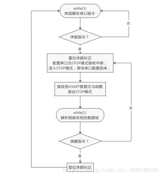
如何使用USART或LPUART从低功耗模式唤醒STM32F0 / F3 / L0 / L4微控制器
官方参考代码
应用平台:STM32F030
main.c
#include "stm32f0xx.h"
/* Private variables ---------------------------------------------------------*/
uint8_t DataReceived = 0;
extern __IO uint8_t InterruptCounter;
/* Private function prototypes -----------------------------------------------*/
static void USART_Config(void);
static void WakeUp_StartBitMethod(void);
static void RestoreConfiguration(void);

/**
  * @brief   Main program
  * @param  None
  * @retval None
  */
int main(void)
{
  /* Initialize LEDs available  ***********************************************/
  STM_EVAL_LEDInit(LED);

  /* USART configuration */
  USART_Config();

  /* Wake up from USART STOP mode by Start bit Method */
  WakeUp_StartBitMethod();

  /* Configure SystemClock*/
  RestoreConfiguration();

  /* Configure and enable the systick timer to generate an interrupt each 1 ms */
  SysTick_Config((SystemCoreClock / 1000));

  while (1)
  {}
}

/**
  * @brief  Start Bit Method to Wake Up USART from Stop mode Test.
  * @param  None
  * @retval None
  */
static void WakeUp_StartBitMethod(void)
{
  /* Configure the wake up Method = Start bit */
  USART_StopModeWakeUpSourceConfig(USART1, USART_WakeUpSource_StartBit);

  /* Enable USART1 */
  USART_Cmd(USART1, ENABLE);

  /* Before entering the USART in STOP mode the REACK flag must be checked to ensure the USART RX is ready */
  while(USART_GetFlagStatus(USART1, USART_FLAG_REACK) == RESET)
  {}

  /* Enable USART STOP mode by setting the UESM bit in the CR1 register.*/
  USART_STOPModeCmd(USART1, ENABLE);

  /* Enable the wake up from stop Interrupt */
  USART_ITConfig(USART1, USART_IT_WU, ENABLE);

  /* Enable PWR APB clock */
  RCC_APB1PeriphClockCmd(RCC_APB1Periph_PWR, ENABLE);

  /* Enter USART in STOP mode with regulator in low power mode */
  PWR_EnterSTOPMode(PWR_Regulator_LowPower, PWR_STOPEntry_WFI);

  /* Waiting Wake Up interrupt */
  while(InterruptCounter == 0x00)
  {}

  /* Disable USART peripheral in STOP mode */
  USART_STOPModeCmd(USART1, DISABLE);

  while(USART_GetFlagStatus(USART1, USART_FLAG_RXNE) == RESET)
  {}
  DataReceived = USART_ReceiveData(USART1);

  /* Clear the TE bit (if a transmission is on going or a data is in the TDR, it will be sent before efectivelly disabling the transmission) */
  USART_DirectionModeCmd(USART1, USART_Mode_Tx, DISABLE);

  /* Check the Transfer Complete Flag */
  while (USART_GetFlagStatus(USART1, USART_FLAG_TC) == RESET)
  {}

  /* USART Disable */
  USART_Cmd(USART1, DISABLE);
}

/**
  * @brief Configure the USART Device
  * @param  None
  * @retval None
  */
static void USART_Config(void)
{
  USART_InitTypeDef USART_InitStructure;
  GPIO_InitTypeDef GPIO_InitStructure;
  NVIC_InitTypeDef NVIC_InitStructure;

  /* Enable GPIO&USART clock */
  RCC_AHBPeriphClockCmd(RCC_AHBPeriph_GPIOA , ENABLE);
  RCC_APB1PeriphClockCmd(RCC_APB2Periph_USART1, ENABLE);

  /* Configure the HSI as USART clock */
  RCC_USARTCLKConfig(RCC_USART2CLK_HSI);

  /* USARTx Pins configuration **************************************************/
  /* Connect pin to Periph */
  GPIO_PinAFConfig(GPIOA, GPIO_PinSource9, GPIO_AF_1);
  GPIO_PinAFConfig(GPIOA, GPIO_PinSource10, GPIO_AF_1);

  /* Configure pins as AF pushpull */
  GPIO_InitStructure.GPIO_Pin = GPIO_Pin_9 | GPIO_Pin_10;
  GPIO_InitStructure.GPIO_Mode = GPIO_Mode_AF;
  GPIO_InitStructure.GPIO_Speed = GPIO_Speed_50MHz;
  GPIO_InitStructure.GPIO_OType = GPIO_OType_PP;
  GPIO_InitStructure.GPIO_PuPd = GPIO_PuPd_NOPULL;
  GPIO_Init(GPIOA, &GPIO_InitStructure);

  /* USARTx configured as follow:
  - BaudRate = 115200 baud
  - Word Length = 8 Bits
  - Stop Bit = 1 Stop Bit
  - Parity = No Parity
  - Hardware flow control disabled (RTS and CTS signals)
  - Receive and transmit enabled
  */

  USART_DeInit(USART1);
  USART_InitStructure.USART_BaudRate = 115200;
  USART_InitStructure.USART_WordLength = USART_WordLength_8b;
  USART_InitStructure.USART_StopBits = USART_StopBits_1;
  USART_InitStructure.USART_Parity = USART_Parity_No;
  USART_InitStructure.USART_HardwareFlowControl = USART_HardwareFlowControl_None;
  USART_InitStructure.USART_Mode = USART_Mode_Rx | USART_Mode_Tx;
  USART_Init(USART1, &USART_InitStructure);

  /* USART2 IRQ Channel configuration */
  NVIC_InitStructure.NVIC_IRQChannel = USART1_IRQn;
  NVIC_InitStructure.NVIC_IRQChannelPriority = 0x01;
  NVIC_InitStructure.NVIC_IRQChannelCmd = ENABLE;
  NVIC_Init(&NVIC_InitStructure);
}

/**
  * @brief  Restore peripheral config before entering STOP mode.
  * @param  None
  * @retval None
  */
static void RestoreConfiguration(void)
{
  __IO uint32_t StartUpCounter = 0, HSEStatus = 0;

  /* SYSCLK, HCLK, PCLK configuration ----------------------------------------*/
  /* Enable HSE */
  RCC_HSEConfig(RCC_HSE_ON);

  /* Wait till HSE is ready and if Time out is reached exit */
  HSEStatus = RCC_WaitForHSEStartUp();

  if (HSEStatus == (uint32_t)0x01)
  {
    /* Enable Prefetch Buffer */
    FLASH_SetLatency(FLASH_Latency_1);

    /* HCLK = SYSCLK */
    RCC_HCLKConfig(RCC_SYSCLK_Div1);

    /* PCLK = HCLK */
    RCC_PCLKConfig(RCC_HCLK_Div1);

    /*  PLL configuration:  = HSE *  6 = 48 MHz */
    RCC_PREDIV1Config(RCC_PREDIV1_Div1);
    RCC_PLLConfig(RCC_PLLSource_PREDIV1, RCC_CFGR_PLLMULL6);

    /* Enable PLL */
    RCC_PLLCmd(ENABLE);

    /* PLL as system clock source */
    RCC_SYSCLKConfig(RCC_SYSCLKSource_PLLCLK);
  }
}
stm32f0xx_it.c
/* Includes ------------------------------------------------------------------*/
#include "stm32f0xx_it.h"
/* Private variables ---------------------------------------------------------*/
__IO uint8_t InterruptCounter = 0x00;
__IO uint8_t Counter = 0;

/**
  * @brief  This function handles SysTick Handler.
  * @param  None
  * @retval None
  */
void SysTick_Handler(void)
{
  if (Counter == 20)
  {
    /* Toggle LED's */
    STM_EVAL_LEDToggle(LED);

    /* Reset Counter */
    Counter = 0;
  }
  else
  {
    /* increment Counter */
    Counter++;
  }
}

/**
* @brief  This function handles USART interrupt request.
* @param  None
* @retval None
*/
void USART1_IRQHandler(void)
{
  if (USART_GetITStatus(USART1, USART_IT_WU) == SET)
  {
    /* Clear The USART WU flag */
    USART_ClearITPendingBit(USART1, USART_IT_WU);
    InterruptCounter = 0x01;
  }
}
实际参考代码
然而,在STM32F030中不能配置为USART的start位唤醒。
#define USART_IT_WU ((uint32_t)0x00140316) /*!< Not available for STM32F030 devices */
解决办法,配置USART的接收非空中断:USART_IT_RXNE