Test equipment
1 test fixture (provide by PIE)
2 Spectrum Analyzer (e.g E4405B)
3.Vector Signal Generator (e.g E4438C)
4.3dB power splitter combiner
5.898/902/920MHz antenna
6.RF cable x 3
7.PC and Serial port line (3.3V)
8.Sigfox Module :WISOL / WSSFM10R1AT
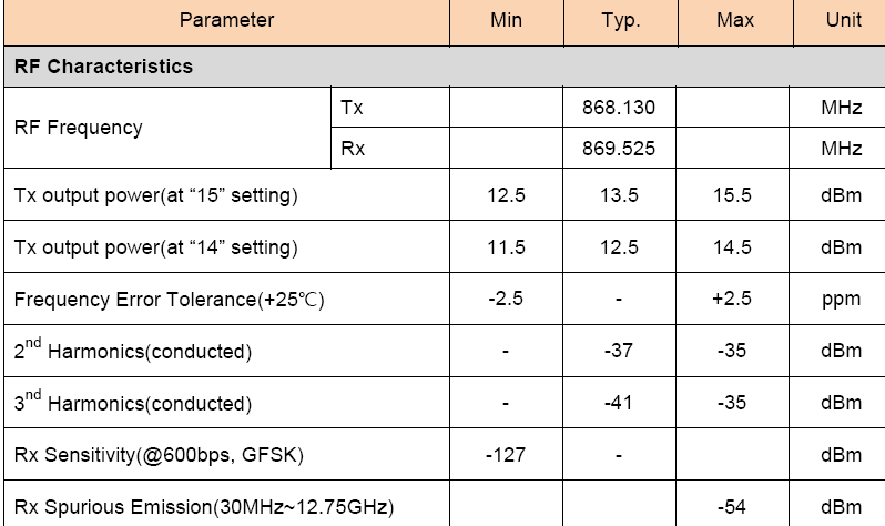
RF Specifications :
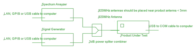
The instrument connection
Spectrum Analyzer Setting:

Sigfox serial port Settings
BaudRate Setting: 9600, 8N1, all AT command send to product has to be ended by ‘\r’ (CR)
TX test:
1 put the gold sample into the test fixture,measure Power and RSSI, and store it as calibration data
2 sending ‘’AT$DR? ‘’ to product
3 sending Tx on command (AT$CW=xxxxx,m,n)
4 Enter :Spectrum Analyzer marker peak search and recording the power and frequency
5 Calculate the frequency PPM

6 sending Tx off command
7 test ok
RX test
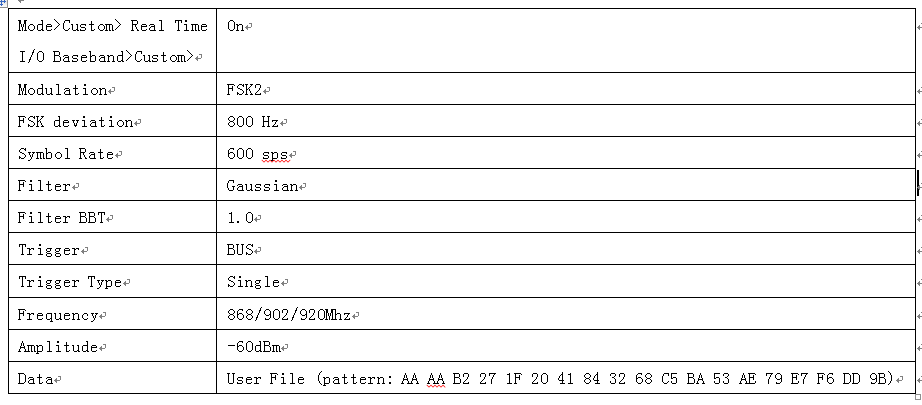
1 Vector Signal Generator Setting:
2 Send Rx start command to the product: AT$TM=3,10. After sending this command, the product will not receive any command in the receiving mode, until 10 seconds later, the product will be returned to the product
3 Signal generator: RF on (after about ten seconds )
4 Trigger Signal Generator sending the data once
5 receive data (RX data and RSSI)
6 Signal generator :RF Off
---------------------------------------------------