Prepare
CAN通信协议使用了有一段时间了,但都是基于软件层面的使用,对于其波形不是很了解,正好这段时间比较闲,是时候补补硬知识。
开始之前,先介绍一下设备:
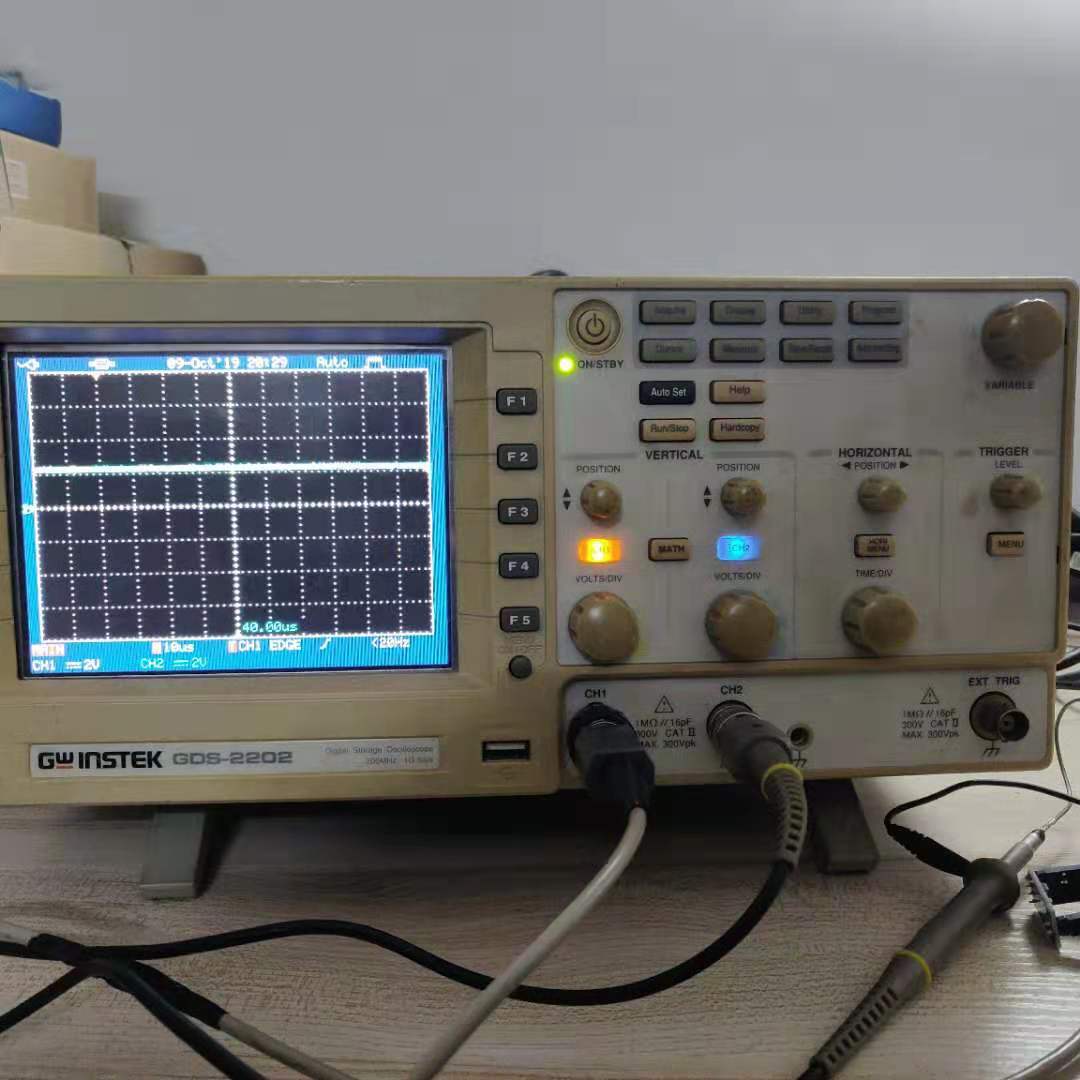
- 咸鱼淘来的古董级别示波器GDS-2202。200MHz,数据记录长度是12500个点(每个点40ns,总记录长度是500us)
- EK-LM4F120XL开发板。也就是现在的EK-TM4C123GXL,板载MCU是TM4C1233H6PM,对应原来的老型号LM4F120H5QR

- CAN收发器,TJA1050模块

Ongoing
软件准备
用CCS9.0导入TI提供的CAN驱动库,每隔1秒钟发送一个CAN信息:
- 波特率:500 kb/s
- ID(Normal): 0x220
- 信息长度 :4 bytes
- 数据:0x12, 0x34, 0x56, 0x78
  1 int main(void)
  2 {
  3     tCANMsgObject sCANMessage;
  4     unsigned char ucMsgData[4];
  5
  6     //
  7     // Set the clocking to run directly from the external crystal/oscillator.
  8     // TODO: The SYSCTL_XTAL_ value must be changed to match the value of the
  9     // crystal on your board.
 10     //
 11     SysCtlClockSet(SYSCTL_SYSDIV_2_5 | SYSCTL_USE_PLL | SYSCTL_OSC_MAIN |
 12                    SYSCTL_XTAL_16MHZ);
 13
 14     //
 15     // Set up the serial console to use for displaying messages.  This is
 16     // just for this example program and is not needed for CAN operation.
 17     //
 18     InitConsole();
 19
 20     //
 21     // For this example CAN0 is used with RX and TX pins on port D0 and D1.
 22     // The actual port and pins used may be different on your part, consult
 23     // the data sheet for more information.
 24     // GPIO port D needs to be enabled so these pins can be used.
 25     // TODO: change this to whichever GPIO port you are using
 26     //
 27     SysCtlPeripheralEnable(SYSCTL_PERIPH_GPIOE);
 28
 29     //
 30     // Configure the GPIO pin muxing to select CAN0 functions for these pins.
 31     // This step selects which alternate function is available for these pins.
 32     // This is necessary if your part supports GPIO pin function muxing.
 33     // Consult the data sheet to see which functions are allocated per pin.
 34     // TODO: change this to select the port/pin you are using
 35     //
 36     GPIOPinConfigure(GPIO_PE4_CAN0RX);
 37     GPIOPinConfigure(GPIO_PE5_CAN0TX);
 38
 39     //
 40     // Enable the alternate function on the GPIO pins.  The above step selects
 41     // which alternate function is available.  This step actually enables the
 42     // alternate function instead of GPIO for these pins.
 43     // TODO: change this to match the port/pin you are using
 44     //
 45     GPIOPinTypeCAN(GPIO_PORTE_BASE, GPIO_PIN_4 | GPIO_PIN_5);
 46
 47     //
 48     // The GPIO port and pins have been set up for CAN.  The CAN peripheral
 49     // must be enabled.
 50     //
 51     SysCtlPeripheralEnable(SYSCTL_PERIPH_CAN0);
 52
 53     //
 54     // Initialize the CAN controller
 55     //
 56     CANInit(CAN0_BASE);
 57
 58     //
 59     // Set up the bit rate for the CAN bus.  This function sets up the CAN
 60     // bus timing for a nominal configuration.  You can achieve more control
 61     // over the CAN bus timing by using the function CANBitTimingSet() instead
 62     // of this one, if needed.
 63     // In this example, the CAN bus is set to 500 kHz.  In the function below,
 64     // the call to SysCtlClockGet() is used to determine the clock rate that
 65     // is used for clocking the CAN peripheral.  This can be replaced with a
 66     // fixed value if you know the value of the system clock, saving the extra
 67     // function call.  For some parts, the CAN peripheral is clocked by a fixed
 68     // 8 MHz regardless of the system clock in which case the call to
 69     // SysCtlClockGet() should be replaced with 8000000.  Consult the data
 70     // sheet for more information about CAN peripheral clocking.
 71     //
 72
 73     sysclk = SysCtlClockGet();
 74     CANBitRateSet(CAN0_BASE, sysclk, 500000);
 75
 76     //
 77     // Enable interrupts on the CAN peripheral.  This example uses static
 78     // allocation of interrupt handlers which means the name of the handler
 79     // is in the vector table of startup code.  If you want to use dynamic
 80     // allocation of the vector table, then you must also call CANIntRegister()
 81     // here.
 82     //
 83     // CANIntRegister(CAN0_BASE, CANIntHandler); // if using dynamic vectors
 84     //
 85     CANIntEnable(CAN0_BASE, CAN_INT_MASTER | CAN_INT_ERROR | CAN_INT_STATUS);
 86
 87     CANRetrySet(CAN0_BASE, false);
 88     //
 89     // Enable the CAN interrupt on the processor (NVIC).
 90     //
 91     IntEnable(INT_CAN0);
 92
 93     //
 94     // Enable the CAN for operation.
 95     //
 96     CANEnable(CAN0_BASE);
 97
 98     //
 99     // Initialize the message object that will be used for sending CAN
100     // messages.  The message will be 4 bytes that will contain an incrementing
101     // value.  Initially it will be set to 0.
102     //
103     *(unsigned long *)ucMsgData = 0;
104     sCANMessage.ulMsgID = 0x220;                    // CAN message ID
105     sCANMessage.ulMsgIDMask = 0;                    // no mask needed for TX
106     sCANMessage.ulFlags = MSG_OBJ_TX_INT_ENABLE;    // enable interrupt on TX
107     sCANMessage.ulMsgLen = sizeof(ucMsgData);       // size of message is 4
108     sCANMessage.pucMsgData = ucMsgData;             // ptr to message content
109
110     ucMsgData[0] = 0x12;
111     ucMsgData[1] = 0x34;
112     ucMsgData[2] = 0x56;
113     ucMsgData[3] = 0x78;
114     //
115     // Enter loop to send messages.  A new message will be sent once per
116     // second.  The 4 bytes of message content will be treated as an unsigned
117     // long and incremented by one each time.
118     //
119     for(;;)
120     {
121         //
122         // Print a message to the console showing the message count and the
123         // contents of the message being sent.
124         //
125         UARTprintf("Sending msg: 0x%02X %02X %02X %02X",
126                    ucMsgData[0], ucMsgData[1], ucMsgData[2], ucMsgData[3]);
127
128         //
129         // Send the CAN message using object number 1 (not the same thing as
130         // CAN ID, which is also 1 in this example).  This function will cause
131         // the message to be transmitted right away.
132         //
133         CANMessageSet(CAN0_BASE, 1, &sCANMessage, MSG_OBJ_TYPE_TX);
134
135         //
136         // Now wait 1 second before continuing
137         //
138         SimpleDelay();
139
140         //
141         // Check the error flag to see if errors occurred
142         //
143         if(g_bErrFlag)
144         {
145             UARTprintf(" error - cable connected?\n");
146         }
147         else
148         {
149             //
150             // If no errors then print the count of message sent
151             //
152             UARTprintf(" total count = %u\n", g_ulMsgCount);
153         }
154
155         //
156         // Increment the value in the message data.
157         //
158         //(*(unsigned long *)ucMsgData)++;
159     }
160
161     //
162     // Return no errors
163     //
164     return(0);
165 }
编译,通过板载调试器下载代码,复位运行代码。

硬件准备
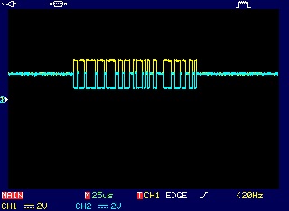
示波器探头CH1连接TJA1050的CANH引脚,探头CH2连接CANL引脚,地跟开发板的GND连接,使用边沿触发模式捕获波形:
分析
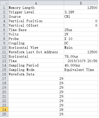
为了方便分析,将波形保存成CSV格式。该CSV文件记录了波形信息和数据,从第17行开始,就是波形的数据,如下图:
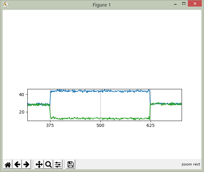
使用Matplotlib导入CSV,绘制折线图,代码如下:
 1 import csv
 2 import matplotlib
 3 import matplotlib.pyplot as plt
 4 import matplotlib.collections as collections
 5 from matplotlib.ticker import MultipleLocator
 6 import numpy as np
 7 import pandas as pd
 8
 9 ax = plt.subplot()
10 #将x主刻度标签设置为125的倍数
11 xmajorLocator = MultipleLocator(125)
12 ax.xaxis.set_major_locator(xmajorLocator)
13 #y轴数据
14 raw_canh = pd.read_csv("canh.csv")
15 raw_canl = pd.read_csv("canl.csv")
16 #x轴数据
17 t = np.arange(130, 12000, 1)
18 ax.plot(t, raw_canh[130:12000], raw_canl[130:12000])
19 ax.xaxis.grid(True)
20
21 plt.show()
运行,效果如下,

局部放大波形图,
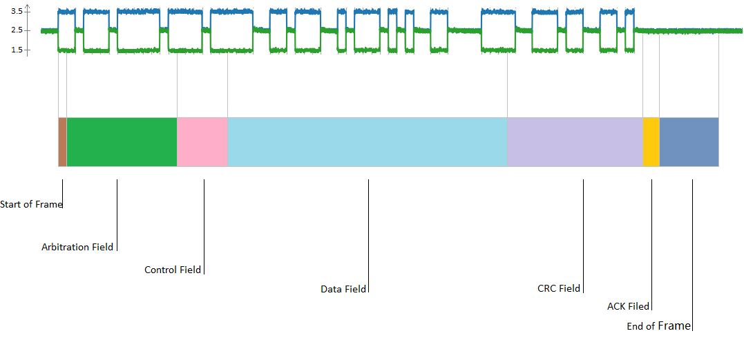
接下来的工作就是PS了,参照CAN2.0B的Spec,找到每一位的定义。首先是整个数据帧(Data Frame)的定义,
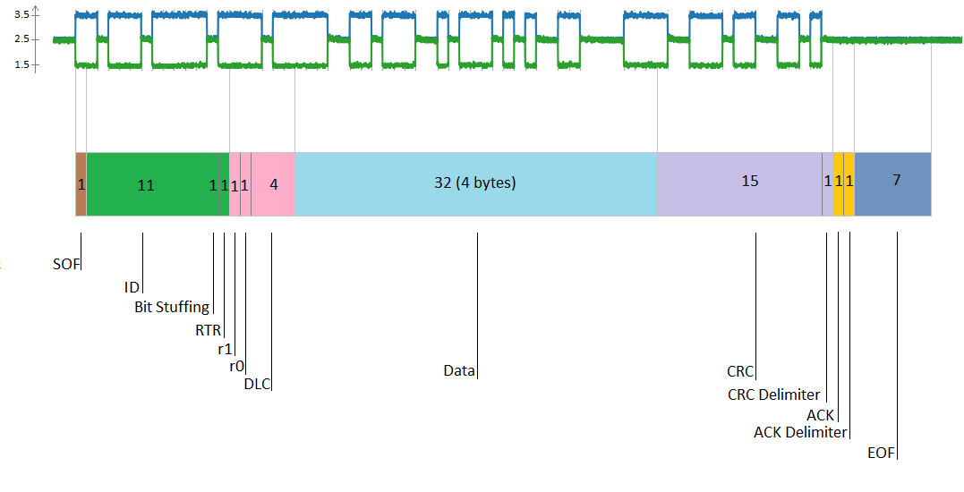
进一步细化每个字段(Field):
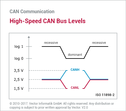
将差分信号转换为实际的二进制值,十六进制值。这里需要补充一点知识,CAN信号电压与实际逻辑的关系,很好记忆,波形像口张开的(O),表示逻辑0(显示);另外一种则表示逻辑1(隐性)。如下图:
根据上面的信息,我们可以进一步得到以下数据,
如果你很细心的看上面图,就会发现一个问题,有些十六进制为什么是有9位?因为有一位是填充位(Bit Stuffing),CAN2.0的协议规定,连续5个显性/隐性电平后,要填充一位隐性/显性电平。如上图中的仲裁字段(Arbitration Field),连续5个'0'后,填充一个'1'。
Post
分析到这里接近尾声了,还有一个疑问,这个CRC校验是怎么算出来的呢?从CAN2.0的Spec了解到,CRC的计算的值从SOF开始,到数据字段(Data Field),多项式:
P(x) = x15+ x14+ x10+ x8+ x7+ x4+ x3+ 1
通过在线CRC计算网站,输入我们的数据,计算CRC的值:
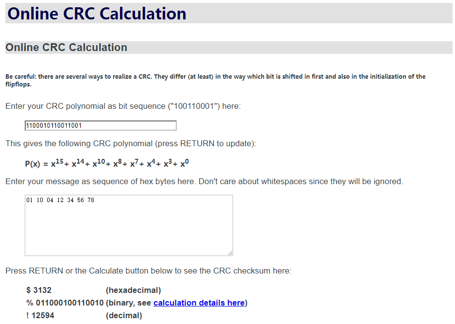
如我们所料,计算的CRC值是正确的!
-----------------------------------------------------------------------------------END
[参考资料]