1.软件版本
ISE14.7
2.本算法实现
研究内容:
1) 设计和验证适合FPGA实现的MSK调制和解调实现方案,
2) MSK系统的发端:含随机数字信息生成模块、MSK调制模块、数模(DA)模块。
3) MSK系统的收端:含MSK解调模块、模数(AD)模块、误码率计算模块。
4) 信道:含功率可控的高斯白噪声(AWGN)生成模块。
5)实现语言:Verilog语言。
需实现的具体内容:
1.用MATLAB进行方案的设计和验证仿真
2.编制基于Verilog的系统(含发端、信道和收端)软件程序;
3进行硬件平台的程序下载和软硬件联调;
扫描二维码关注公众号,回复:
14239127 查看本文章

4利用测试设备,完成MSK系统各关键模块的输入和输出波形、功率谱的测量;
5仿照FPGA平台的硬件结构和布局,设计FGPA最小开发平台,并绘制其PCB电路图。
调制端的结构如下所示:
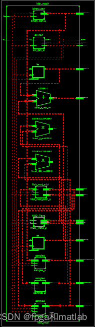
仿真结果如下所示:
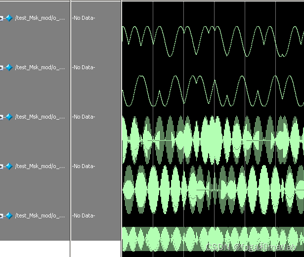
仿真结果可以看到,MSK调制端是完全正确的。
该部分程序如下:
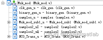
程序中,顶层模块的调用,我们做了注释。
MSK解调部分按之前的系统框图进行设计。设计完的基本构架如下所示:
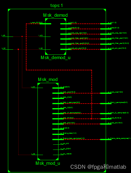
上述的构架就是整个系统的调制解调系统,其中解调端的仿真结果如下所示:

3.部分源码
`timescale 1ns / 1ps
//
// Company:
// Engineer:
//
// Create Date:    15:16:09 06/09/2013
// Design Name:
// Module Name:    Msk_mod
// Project Name:
// Target Devices:
// Tool versions:
// Description:
//
// Dependencies:
//
// Revision:
// Revision 0.01 - File Created
// Additional Comments:
//
//
module Msk_mod(
               i_clk,     //40M
					i_rst,     //rst signal
					o_clk_4M,  //MSK rate
					o_clk_1600K,//bit rate samples
					o_clk_200K, //bit rate
					o_Trans_data,//the binary data
					o_Trans_data_samples,//the binary data samples
					o_Msk_I,             //MSK I
					o_Msk_Q,             //MSK Q samples
					o_Msk_I_samples,     //MSK I
					o_Msk_Q_samples,		//MSK Q samples
					o_cos,               //cos
					o_sin,               //sin
					o_msk_cos,           //MSK Cos
					o_msk_sin,           //MSK Sin
					o_msk_R              //MSK frequency
	           );

input              i_clk;
input              i_rst;
output             o_clk_4M;
output             o_clk_1600K;
output             o_clk_200K;
output signed[1:0] o_Trans_data;
output signed[1:0] o_Trans_data_samples;
output signed[9:0] o_Msk_I;
output signed[9:0] o_Msk_Q;
output signed[9:0] o_Msk_I_samples;
output signed[9:0] o_Msk_Q_samples;
output signed[9:0] o_cos;
output signed[9:0] o_sin;
output signed[15:0]o_msk_cos;
output signed[15:0]o_msk_sin;
output signed[15:0]o_msk_R;

//generate the data rate clock and the fc clock
clk_gen clk_gen_u(
					  .i_clk      (i_clk),
					  .i_rst      (i_rst),
					  .o_clk_4M   (o_clk_4M),
					  .o_clk_1600K(o_clk_1600K),
					  .o_clk_200K (o_clk_200K)
					 );

//generate the random data
binary_gen binary_gen_u(
							   .i_clk (o_clk_200K),
							   .i_rst (i_rst),
							   .o_dout(o_Trans_data)
							  );

//samples the data from low data to high data
samples samples_u(
    .i_clk    (o_clk_1600K),
    .i_rst    (i_rst),
    .i_din    (o_Trans_data),
    .o_dout   (o_Trans_data_samples)
    );

//gen MSK I data and Q data
Msk_mod_sub1 Msk_mod_sub1_u(
    .i_clk  (o_clk_1600K),
    .i_rst  (i_rst),
    .i_data (o_Trans_data_samples),
    .o_mskI (o_Msk_I),
    .o_mskQ (o_Msk_Q)
    );


//samples the data from low data to high data
samples2 samples2_uI(
    .i_clk    (o_clk_4M),
    .i_rst    (i_rst),
    .i_din    (o_Msk_I),
    .o_dout   (o_Msk_I_samples)
    );

//samples the data from low data to high data
samples2 samples2_uQ(
    .i_clk    (o_clk_4M),
    .i_rst    (i_rst),
    .i_din    (o_Msk_Q),
    .o_dout   (o_Msk_Q_samples)
    );


//Mults
NCO_Trans NCO_Trans_u(
    .i_clk   (o_clk_4M),
    .i_rst   (i_rst),
    .o_cos   (o_cos),
    .o_sin   (o_sin)
    );


//MSK Frequency data
reg signed[19:0]II;
reg signed[19:0]QQ;
always @(posedge o_clk_4M or posedge i_rst)
begin
     if(i_rst)
	  begin
	  II <= 20'd0;
	  QQ <= 20'd0;
	  end
else begin
	  II <= o_cos*o_Msk_I_samples;
	  QQ <= o_sin*o_Msk_Q_samples;
     end
end


assign o_msk_cos = II[19:4];
assign o_msk_sin = QQ[19:4];
assign o_msk_R   = {o_msk_cos[15],o_msk_cos[15:1]}+{o_msk_sin[15],o_msk_sin[15:1]};


endmodule
`timescale 1ns / 1ps
//
// Company:
// Engineer:
//
// Create Date:    15:16:19 06/09/2013
// Design Name:
// Module Name:    Msk_demod
// Project Name:
// Target Devices:
// Tool versions:
// Description:
//
// Dependencies:
//
// Revision:
// Revision 0.01 - File Created
// Additional Comments:
//
//
module Msk_demod(
                 i_clk,
					  i_rst,
					  i_msk_R,
					  o_msk_cos_rec,
	              o_msk_sin_rec,
					  o_msk_filter_recI,
					  o_msk_filter_recQ,
					  o_data,
					  o_bit
	             );

input              i_clk;
input              i_rst;
input  signed[15:0]i_msk_R;
output signed[15:0]o_msk_cos_rec;
output signed[15:0]o_msk_sin_rec;
output signed[15:0]o_msk_filter_recI;
output signed[15:0]o_msk_filter_recQ;
output signed[31:0]o_data;
output signed[1:0] o_bit;

reg signed[31:0]err;


//generate the data rate clock and the fc clock
wire clk_4M;	     //10
wire clk_1600K;	  //25
wire clk_200K;      //200
clk_gen clk_gen_u(
					  .i_clk      (i_clk),
					  .i_rst      (i_rst),
					  .o_clk_4M   (clk_4M),
					  .o_clk_1600K(clk_1600K),
					  .o_clk_200K (clk_200K)
					 );

//Mults
wire signed[9:0]cos;
wire signed[9:0]sin;
NCO_Rec NCO_Rec_u(
    .i_clk   (clk_4M),
    .i_rst   (i_rst),
    .i_phase (err[31:21]),
    .o_cos   (cos),
    .o_sin   (sin)
    );


//MSK Frequency data
reg signed[19:0]II;
reg signed[19:0]QQ;
always @(posedge clk_4M or posedge i_rst)
begin
     if(i_rst)
	  begin
	  II <= 20'd0;
	  QQ <= 20'd0;
	  end
else begin
	  II <= cos*i_msk_R;
	  QQ <= sin*i_msk_R;
     end
end


assign o_msk_cos_rec = II[18:3];
assign o_msk_sin_rec = QQ[18:3];


Filter Filter_u1(
    .i_clk(clk_4M),
    .i_rst(i_rst),
    .i_din(o_msk_cos_rec),
    .o_dout(o_msk_filter_recI)
    );

Filter Filter_u2(
    .i_clk(clk_4M),
    .i_rst(i_rst),
    .i_din(o_msk_sin_rec),
    .o_dout(o_msk_filter_recQ)
    );


reg signed[31:0]err1;
reg signed[31:0]err2;

always @(posedge i_clk or posedge i_rst)
begin
     if(i_rst)
	  begin
	  err1 <= 32'd0;
	  err2 <= 32'd0;
	  end
else begin
     err1 <= o_msk_filter_recI*o_msk_filter_recQ;
	  err2 <= err1;
	  err  <= 48*err1 + 128*(err1 - err2);
     end
end


data_check data_check_u(
    .i_clk_200K(clk_200K),
    .i_rst(i_rst),
    .i_filterI(o_msk_filter_recI),
    .i_filterQ(o_msk_filter_recQ),
    .o_dout(o_data),
    .o_bit(o_bit)
    );


endmodule
4.参考文献
[1]贾志强, 郭莉, 陈文志. 基于FPGA/DDS技术的MSK信号调制与解调[J]. 微计算机信息, 2009(29):3.A01-117