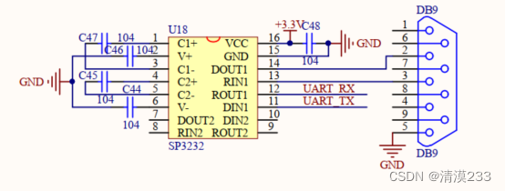
上图为芯片TTL电压转换为串口RS232电压,该DB9为母口,通过串口转USB线连接到电脑PC端上。
目的:使用dspic33fj32mc204与PC端进行通信,然后使用串口调试助手进行收发数据
程序如下(注意:下面程序与MIRCOCHIP公司的dspic33f系列数据手册的程序有些不同,是在它基础上的补充说明和改进bug):
#include "p33FJ32MC204.h"
#include "dsp.h"
#include <xc.h>
#include <PPS.H>
/*****************Config bit settings****************/
// FBS
#pragma config BWRP = WRPROTECT_OFF     // Boot Segment Write Protect (Boot Segment may be written)
#pragma config BSS = NO_FLASH           // Boot Segment Program Flash Code Protection (No Boot program Flash segment)

// FGS
#pragma config GWRP = OFF               // General Code Segment Write Protect (User program memory is not write-protected)
#pragma config GSS = OFF                // General Segment Code Protection (User program memory is not code-protected)

// FOSCSEL
#pragma config FNOSC = FRC             //
#pragma config IESO = ON                // 使用内部FRC振荡源启动器件,然后自动切换为就绪的用户选择的振荡器源 Internal External Switch Over Mode (Start-up device with FRC, then automatically switch to user-selected oscillator source when ready)

// FOSC
#pragma config POSCMD = XT              //
#pragma config OSCIOFNC = OFF           // OSC2 Pin Function (OSC2 pin has clock out function)
#pragma config IOL1WAY = OFF            //
#pragma config FCKSM = CSECME           //

// FWDT
#pragma config FWDTEN = OFF             //
// FPOR
#pragma config FPWRT = PWR128           // POR Timer Value (128ms)
#pragma config ALTI2C = OFF             // Alternate I2C  pins (I2C mapped to SDA1/SCL1 pins)
#pragma config LPOL = ON                // Motor Control PWM Low Side Polarity bit (PWM module low side output pins have active-high output polarity)
#pragma config HPOL = ON                // Motor Control PWM High Side Polarity bit (PWM module high side output pins have active-high output polarity)
#pragma config PWMPIN = ON              // Motor Control PWM Module Pin Mode bit (PWM module pins controlled by PORT register at device Reset)

// FICD
#pragma config ICS = PGD3               // Comm Channel Select (Communicate on PGC1/EMUC1 and PGD1/EMUD1)
#pragma config JTAGEN = OFF             // JTAG Port Enable (JTAG is Disabled)

#define FCY 40000000
#define BAUDRATE 9600
#define BRGVAL ((FCY/BAUDRATE)/16)-1
unsigned int i;


void __attribute__((__interrupt__,no_auto_psv)) _U1RXInterrupt( void );
void __attribute__((__interrupt__)) _U1TXInterrupt( void );
void __attribute__((__interrupt__,no_auto_psv)) _T1Interrupt(void);
char ReceivedChar;

int main(void)
{
        //Perform a clock switch to 40MIPS (80Mhz)外部晶振电路图上是7.3728MHZ(FIN)但是实际板子上是8MHZ
	PLLFBD = 38;			//M=PLLFBD+2       = 40
	CLKDIVbits.PLLPOST = 0;	//N2=2(PLLPOST+1)  = 2
	CLKDIVbits.PLLPRE = 0;	//N1=PLLPRE+2      = 2

        OSCTUN=0; // Tune FRC oscillator, if FRC is used
        RCONbits.SWDTEN=0; // Disable Watch Dog Timer

        //unlock OSCCON register
	__builtin_write_OSCCONH(0x03);//切换到带PLL的主振荡器模式   经过测试 应该切换成功了
	__builtin_write_OSCCONL(0x01);//时钟切换被使能,外设引脚未锁定,允许写入外设引脚选择寄存器,PLL处于失锁状态,禁止辅助振荡器,请求切换新的振荡器
    //wait for clock to stabilize
	while(OSCCONbits.COSC != 0b011);
	//wait for PLL to lock
	while(OSCCONbits.LOCK != 1) {};
    //clock switch finished

        TRISBbits.TRISB4 = 1;//RP4输入
        TRISCbits.TRISC5 = 0;//RP21输出

        TRISBbits.TRISB15 = 0;
        TRISBbits.TRISB14 = 0;
        //UART
        //UART外设引脚选择
        PPSUnLock;
        RPINR18bits.U1RXR = 4;//UART1接收
        _RP21R = 0b00011;//UART1发送
        PPSLock;

        //UART发送配置
        //UxMODE UARTx模式寄存器
        //_USIDL = 1;//器件进入空闲模式时,模块停止工作
        //_UEN = 0;// 使能并使用 UxTX 和 UxRX 引脚; UxCTS、 UxRTS 和 BCLKx 引脚由端口锁存器控制
        //_LPBACK = 0;//禁止环回模式
        _ABAUD = 0;//禁止自动波特率使能位
        //U1STAbits.UTXINV = 0;//UxTX的空闲状态为0
        //_URXINV = 1;//UxRX的空闲状态为0
        _BRGH = 0;//波特率选择为低速
        U1BRG = BRGVAL;//波特率设置为9600
        _PDSEL = 0;//8位数据,无奇偶校验位
        _STSEL = 0;//1个停止位
        //UxSTA UARTx状态和控制寄存器
        U1STAbits.UTXISEL0 = 0b0;//当一个字符被传输到发送移位寄存器时,意味着发送缓冲器至少有一个单元为空,产生中断
        U1STAbits.UTXISEL1 = 0b0;
        //U1STAbits.UTXINV = 0;//UxTX的空闲状态为0
        //U1STAbits.UTXBRK = 1;//发送间隔位,无论发送器状态如何,都将UxTX引脚驱动为低电平
        //IPC3bits.U1TXIP = 3;//接收器自然优先级比发送器高
        IEC0bits.U1TXIE = 1;
        _UARTEN = 1;//使能UART1 当模块第一次使能时,用户应用程序应在ISR中清零U1TXIF位
        _UTXEN = 1;//使能UART1发送器,由UARTx控制UxTX引脚,如果UTXISEL为00将UxTXIF位置1

        /* wait at least 104 usec (1/9600) before sending first char */
        for(i=0;i<4160;i++)
        {
            Nop();
        }
        U1TXREG = '1';

        //UART接收配置
//        IPC2bits.U1RXIP = 4;
        IEC0bits.U1RXIE = 1;
        IFS0bits.U1RXIF = 0;
        U1STAbits.URXISEL = 0;

        while(1)
        {
            /* check for receive errors */
            if(U1STAbits.FERR == 1)//检测到当前字符的帧错误
            {
                continue;
            }
            /* must clear the overrun error to keep uart receiving */
            if(U1STAbits.OERR == 1)//如果接收缓冲区已经溢出
            {
                U1STAbits.OERR = 0;//清零原来置1的OEER位将使接收缓冲区和RSR复位为空状态
                continue;
            }
            /* get the data */
            if(U1STAbits.URXDA == 1)
            {
                ReceivedChar = U1RXREG;
            }
        }

        while(1);
        return(0) ;

}


void __attribute__((__interrupt__,no_auto_psv)) _U1TXInterrupt(void)
{
    IFS0bits.U1TXIF = 0;
    for(i=0;i<4160;i++)
       {
            Nop();
        }
    U1TXREG = '1';
    //PORTBbits.RB14 = !PORTBbits.RB14;
}

void __attribute__((__interrupt__,no_auto_psv)) _U1RXInterrupt(void)
{
    IFS0bits.U1RXIF = 0;

   if (ReceivedChar == 'a')
   {PORTBbits.RB15 = !PORTBbits.RB15;}
}
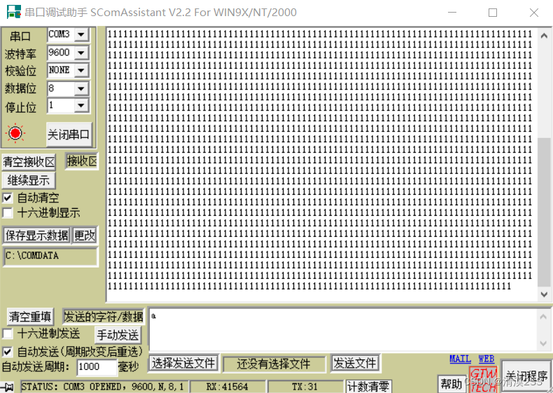
程序说明:配置UART的收发程序,电路板芯片通过串口和PC进行通信,发送字符1到PC端,PC端也可发送字符a到芯片,如果接收到了正确的字符a,那么RB15对应的LED灯亮或灭。
下面是PC端接收和发送: