Reference:
Schematic diagram in allegro and interaction of components in pcb
1 Introduction
The so-called interaction is like this, click a component in the schematic diagram, and it will be selected accordingly in the PCB diagram, which can provide us with great convenience when the components are just imported into the PCB layout and placement of components. And we can partition the layout according to the functional modules of the schematic diagram in the PCB through interaction, which is very convenient.
2. Interaction between schematic and PCB
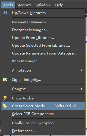
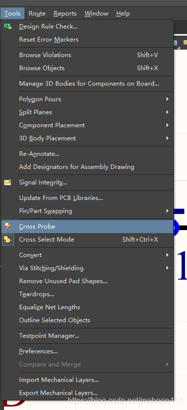
First set the interactive mode. Click Tools→Cross Select Mode.
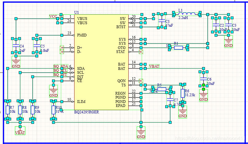
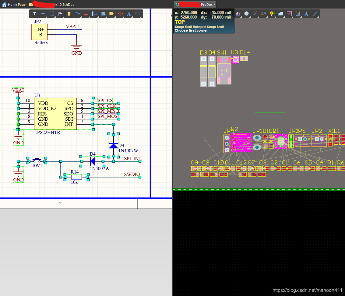
Then select a functional module in the schematic diagram, for example, I select the power management module.
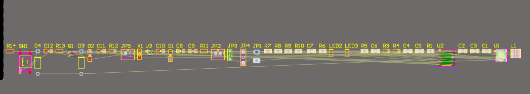
Then switch to the PCB, and you will find that the power management related devices have been highlighted.
Click Tools→Component Placement→Arrange Within Rectangle
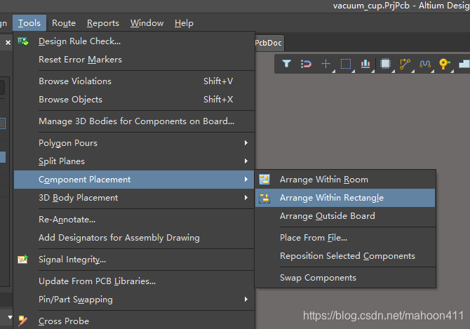
in turn, a green cross will appear on the screen.
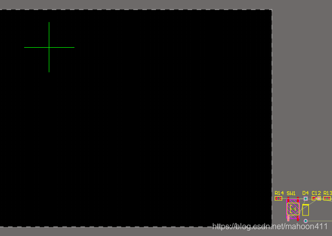
Use this cross to draw a box, and the device you just selected will appear in this box.
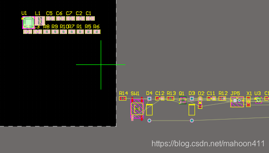
In this way, the interaction between the schematic diagram and the PCB is realized.
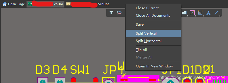
To facilitate interaction, you can right-click on the file bar and click Split Vertical to achieve vertical split screen.
If you want to know the location of an element in the PCB in the schematic, you can use the cross probe.
Press Tools→Cross Probe in sequence, or press the shortcut key TC.
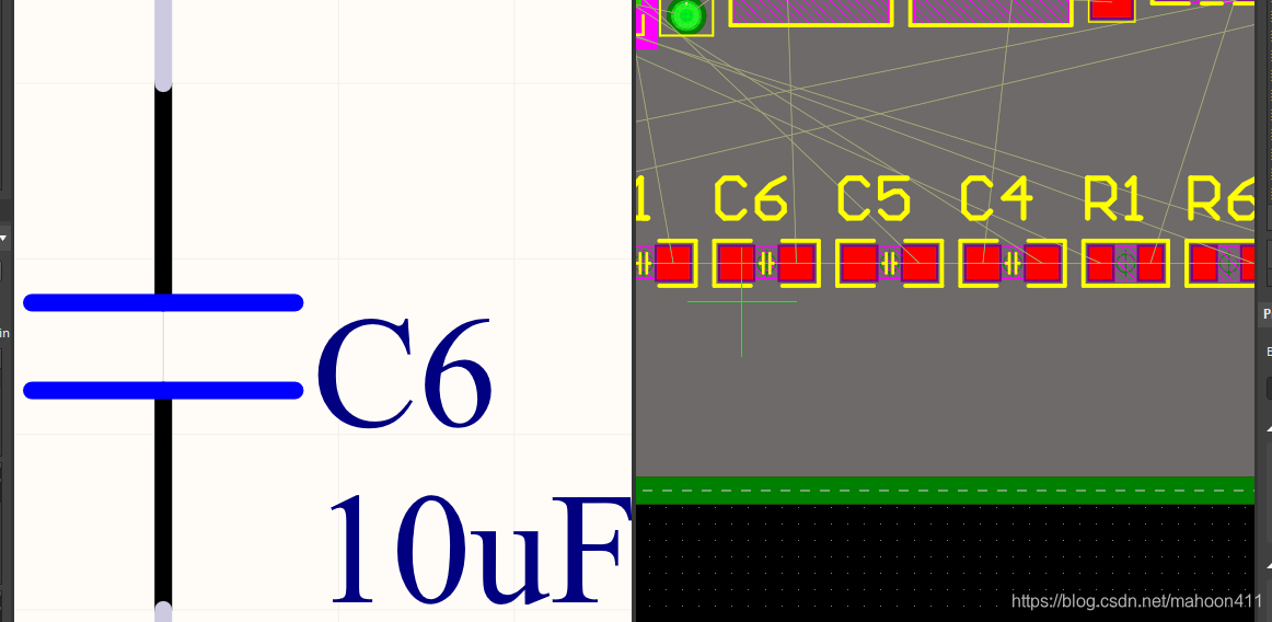
Then click on the component in the PCB.
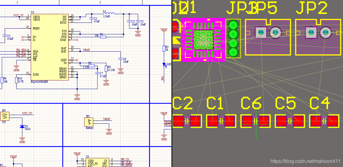
At this time, the corresponding components in the PCB will be highlighted in the schematic diagram.
Similarly, if you want to know the position of a component in the schematic diagram on the PCB, click the component in the schematic diagram in the same way, and the corresponding component in the schematic diagram will be highlighted in the PCB.