Table of contents
1. Experimental environment
hardware environment
FPGA development board: EP4CE115F29C7
LCD display, VGA transmission line
Software Environment
Quartus Prime 18.1
VS Code
Chinese lattice generation website: https://www.zhetao.com/fontarray.html
Picture format bmp to hex software: BMP2Mif
2. Introduction to VGA
1. What is VGA
VGA (Video Graphics Array) is a video transmission standard introduced by IBM together with PS/2 machine in 1987. It has the advantages of high resolution, fast display speed and rich colors, and has been widely used in the field of color displays. Does not support hot plugging, does not support audio transmission. For some embedded VGA display systems, the display and control of VGA images can be realized without using a VGA display card and a computer. VGA display has the advantages of low cost, simple structure and flexible application. For an FPGA engineer, especially a learner in the direction of video images, the VGA protocol must be mastered.
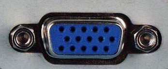
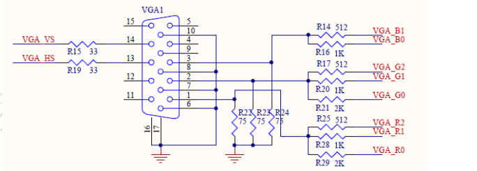
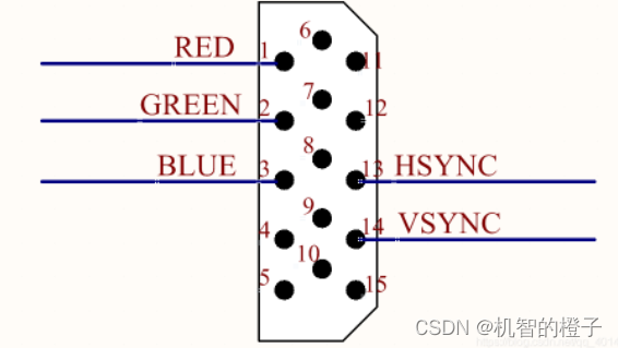
As can be seen from the circuit diagram, VGA does not have a special external chip, and we need to pay attention to only 5 signals: HS horizontal synchronization signal, VS vertical synchronization signal, R red primary color, G green primary color, and B blue primary color. These signals are explained slowly below.
2. VGA display principle
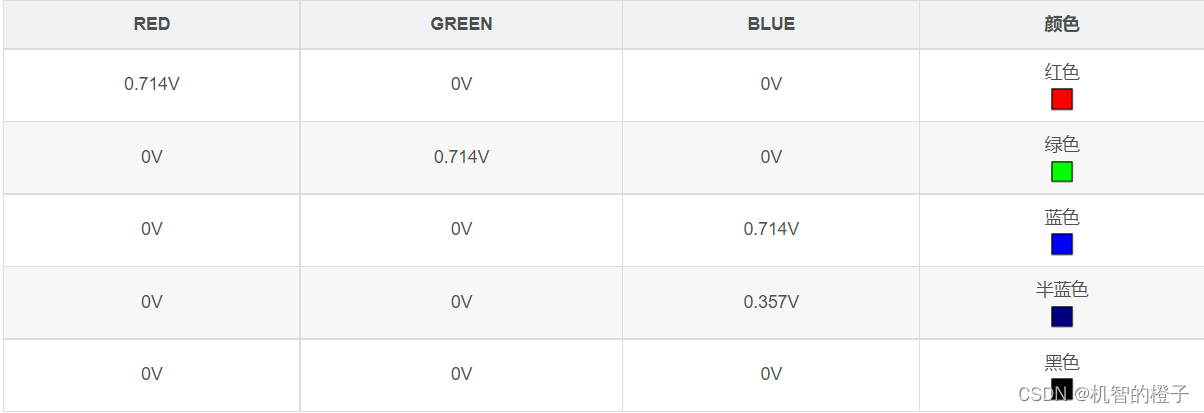
VGA displays three colors of red, green and blue through the analog voltage (0V-0.714V) of the pin, and different voltage values correspond to different colors.
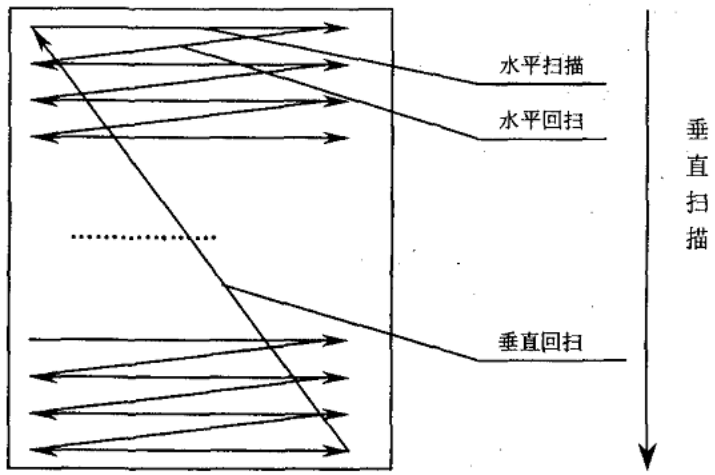
VGA drives the display using a scanning method, usually progressive scanning.
Progressive scanning starts from a point in the upper left corner of the screen, and scans point by point from the left image to the right. After each line is scanned, the electron beam returns to the starting position of the next line on the left side of the screen. During this period, the CRT blanks the electron beam , at the end of each line, use the line synchronization signal for synchronization;
when all the lines are scanned to form a frame, use the field synchronization signal for field synchronization, and make the scan return to the upper left of the screen, and at the same time perform field blanking, and start the next frame.
The FPGA chip drives the VGA display, and it needs to generate an analog signal first, which requires the help of a digital-to-analog converter D/A, and uses the D/A to generate an analog signal, which is output to the RED, GREEN, BLUE primary color data lines of the VGA. Another method is to use the resistor network to shunt the analog D/A.
When designing RGB signals, you can assign R signals, G signals and B signals independently, and finally connect them to the port, or you can directly use RGB as a whole signal. There are three common formats for the bit width of RGB signals in use. The configuration of the VGA decoder chip is related.
1. RGB_8,R:G:B = 3:3:2,即RGB332
2. RGB_16, R:G:B = 5:6:5, namely RGB565
3. RGB_24, R:G:B = 8:8:8, namely RGB888
3. Scanning method
VGA display scanning methods are divided into progressive scan and interlaced scan: progressive scan starts from a point in the upper left corner of the screen, and scans point by point from the left image to the right. After each line is scanned, the electron beam returns to the left side of the screen to start the next line. Position, during this period, the CRT blanks the electron beam, and at the end of each line, it is synchronized with the line synchronization signal; when all the lines are scanned, a frame is formed, and the field synchronization signal is used for field synchronization, and the scan returns to the screen At the top left, vertical blanking is performed at the same time, and the next frame starts. Interlaced scanning means that when the electron beam scans, it scans every other line. After completing a screen, it returns to scan the remaining lines. The interlaced scanning display flickers violently, which will make the user's eyes tired. Therefore, we generally use progressive scanning.
Three, VGA display characters
The Chinese character lattice is used here, and the Chinese character lattice needs to be taken:
https://www.zhetao.com/fontarray.html
Input the required characters to obtain the corresponding Chinese character dot matrix:
The dot matrix program used in the code is shown in the figure: delete the 0x and the comma to keep this format, and paste it into the code.
code show as below:
module VGA_View_name(
OSC_50, //原CLK2_50时钟信号
VGA_CLK, //VGA自时钟
VGA_HS, //行同步信号
VGA_VS, //场同步信号
VGA_BLANK, //复合空白信号控制信号 当BLANK为低电平时模拟视频输出消隐电平,此时从R9~R0,G9~G0,B9~B0输入的所有数据被忽略
VGA_SYNC, //符合同步控制信号 行时序和场时序都要产生同步脉冲
VGA_R, //VGA绿色
VGA_B, //VGA蓝色
VGA_G); //VGA绿色
input OSC_50; //外部时钟信号CLK2_50
output VGA_CLK,VGA_HS,VGA_VS,VGA_BLANK,VGA_SYNC;
output [7:0] VGA_R,VGA_B,VGA_G;
parameter H_FRONT = 16; //行同步前沿信号周期长
parameter H_SYNC = 96; //行同步信号周期长
parameter H_BACK = 48; //行同步后沿信号周期长
parameter H_ACT = 640; //行显示周期长
parameter H_BLANK = H_FRONT+H_SYNC+H_BACK; //行空白信号总周期长
parameter H_TOTAL = H_FRONT+H_SYNC+H_BACK+H_ACT; //行总周期长耗时
parameter V_FRONT = 11; //场同步前沿信号周期长
parameter V_SYNC = 2; //场同步信号周期长
parameter V_BACK = 31; //场同步后沿信号周期长
parameter V_ACT = 480; //场显示周期长
parameter V_BLANK = V_FRONT+V_SYNC+V_BACK; //场空白信号总周期长
parameter V_TOTAL = V_FRONT+V_SYNC+V_BACK+V_ACT; //场总周期长耗时
reg [10:0] H_Cont; //行周期计数器
reg [10:0] V_Cont; //场周期计数器
wire [7:0] VGA_R; //VGA红色控制线
wire [7:0] VGA_G; //VGA绿色控制线
wire [7:0] VGA_B; //VGA蓝色控制线
reg VGA_HS;
reg VGA_VS;
reg [10:0] X; //当前行第几个像素点
reg [10:0] Y; //当前场第几行
reg CLK_25;
always@(posedge OSC_50)
begin
CLK_25=~CLK_25; //时钟
end
assign VGA_SYNC = 1'b0; //同步信号低电平
assign VGA_BLANK = ~((H_Cont<H_BLANK)||(V_Cont<V_BLANK)); //当行计数器小于行空白总长或场计数器小于场空白总长时,空白信号低电平
assign CLK_to_DAC = CLK_25;
assign VGA_CLK = ~CLK_to_DAC; //VGA时钟等于CLK_25取反
always@(posedge CLK_to_DAC)
begin
if(H_Cont<H_TOTAL) //如果行计数器小于行总时长
H_Cont<=H_Cont+1'b1; //行计数器+1
else H_Cont<=0; //否则行计数器清零
if(H_Cont==H_FRONT-1) //如果行计数器等于行前沿空白时间-1
VGA_HS<=1'b0; //行同步信号置0
if(H_Cont==H_FRONT+H_SYNC-1) //如果行计数器等于行前沿+行同步-1
VGA_HS<=1'b1; //行同步信号置1
if(H_Cont>=H_BLANK) //如果行计数器大于等于行空白总时长
X<=H_Cont-H_BLANK; //X等于行计数器-行空白总时长 (X为当前行第几个像素点)
else X<=0; //否则X为0
end
always@(posedge VGA_HS)
begin
if(V_Cont<V_TOTAL) //如果场计数器小于行总时长
V_Cont<=V_Cont+1'b1; //场计数器+1
else V_Cont<=0; //否则场计数器清零
if(V_Cont==V_FRONT-1) //如果场计数器等于场前沿空白时间-1
VGA_VS<=1'b0; //场同步信号置0
if(V_Cont==V_FRONT+V_SYNC-1) //如果场计数器等于行前沿+场同步-1
VGA_VS<=1'b1; //场同步信号置1
if(V_Cont>=V_BLANK) //如果场计数器大于等于场空白总时长
Y<=V_Cont-V_BLANK; //Y等于场计数器-场空白总时长 (Y为当前场第几行)
else Y<=0; //否则Y为0
end
reg valid_yr;
always@(posedge CLK_to_DAC)
if(V_Cont == 10'd32) //场计数器=32时
valid_yr<=1'b1; //行输入激活
else if(V_Cont==10'd512) //场计数器=512时
valid_yr<=1'b0; //行输入冻结
wire valid_y=valid_yr; //连线
reg valid_r;
always@(posedge CLK_to_DAC)
if((H_Cont == 10'd32)&&valid_y) //行计数器=32时
valid_r<=1'b1; //像素输入激活
else if((H_Cont==10'd512)&&valid_y) //行计数器=512时
valid_r<=1'b0; //像素输入冻结
wire valid = valid_r; //连线
wire[10:0] x_dis; //像素显示控制信号
wire[10:0] y_dis; //行显示控制信号
assign x_dis=X; //连线X
assign y_dis=Y; //连线Y
parameter
char_line00=240'h004000400000000000000000000000000000000000000000000000000000,
char_line01=240'h784020a00000000000000000000000000000000000000000000000000000,
char_line02=240'h484011100000000000000000000000000000000000000000000000000000,
char_line03=240'h57fe1208000018003c003c00180018007e001800180018007e003c000400,
char_line04=240'h508085f60000240042004200240024004200240024002400400042000c00,
char_line05=240'h612048000000400042004200420042000400420040004200400042000c00,
char_line06=240'h512047c40000400002004200420042000400420040004200400002001400,
char_line07=240'h4a20145400005c000400020042004200080042005c004200780004002400,
char_line08=240'h4bfc14547e00620018000400420042000800420062004200440018002400,
char_line09=240'h482027d40000420004000800420042001000420042004200020004004400,
char_line0a=240'h6928e4540000420002001000420042001000420042004200020002007f00,
char_line0b=240'h512424540000420042002000420042001000420042004200420042000400,
char_line0c=240'h422227d40000220042004200240024001000240022002400440042000400,
char_line0d=240'h4422244400001c003c007e0018001800100018001c00180038003c001f00,
char_line0e=240'h40a025540000000000000000000000000000000000000000000000000000,
char_line0f=240'h404004880000000000000000000000000000000000000000000000000000;
reg[7:0] char_bit;
always@(posedge CLK_to_DAC)
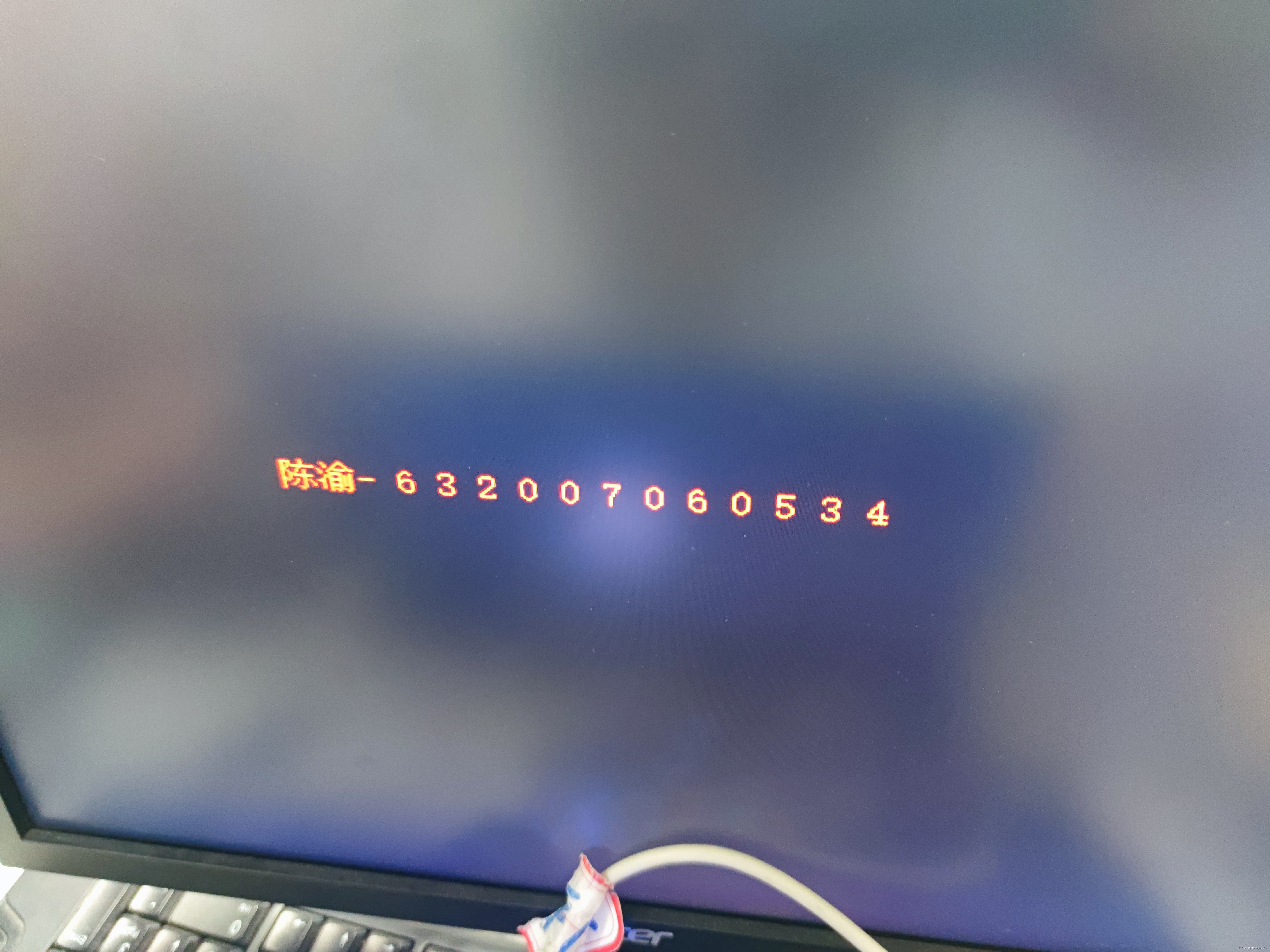
if(X==10'd180)char_bit<=9'd240; //当显示到144像素时准备开始输出图像数据
else if(X>10'd180&&X<10'd420) //左边距屏幕144像素到416像素时 416=144+272(图像宽度)
char_bit<=char_bit-1'b1; //倒着输出图像信息
reg[29:0] vga_rgb; //定义颜色缓存
always@(posedge CLK_to_DAC)
if(X>10'd180&&X<10'd420) //X控制图像的横向显示边界:左边距屏幕左边144像素 右边界距屏幕左边界416像素
begin case(Y) //Y控制图像的纵向显示边界:从距离屏幕顶部160像素开始显示第一行数据
10'd200:
if(char_line00[char_bit])vga_rgb<=30'b1111111111_0000000000_0000000000; //如果该行有数据 则颜色为红色
else vga_rgb<=30'b0000000000_0000000000_0000000000; //否则为黑色
10'd201:
if(char_line01[char_bit])vga_rgb<=30'b1111111111_0000000000_0000000000;
else vga_rgb<=30'b0000000000_0000000000_0000000000;
10'd202:
if(char_line02[char_bit])vga_rgb<=30'b1111111111_0000000000_0000000000;
else vga_rgb<=30'b0000000000_0000000000_0000000000;
10'd203:
if(char_line03[char_bit])vga_rgb<=30'b1111111111_0000000000_0000000000;
else vga_rgb<=30'b0000000000_0000000000_0000000000;
10'd204:
if(char_line04[char_bit])vga_rgb<=30'b1111111111_0000000000_0000000000;
else vga_rgb<=30'b0000000000_0000000000_0000000000;
10'd205:
if(char_line05[char_bit])vga_rgb<=30'b1111111111_0000000000_0000000000;
else vga_rgb<=30'b0000000000_0000000000_0000000000;
10'd206:
if(char_line06[char_bit])vga_rgb<=30'b1111111111_0000000000_0000000000;
else vga_rgb<=30'b0000000000_0000000000_0000000000;
10'd207:
if(char_line07[char_bit])vga_rgb<=30'b1111111111_0000000000_0000000000;
else vga_rgb<=30'b0000000000_0000000000_0000000000;
10'd208:
if(char_line08[char_bit])vga_rgb<=30'b1111111111_0000000000_0000000000;
else vga_rgb<=30'b0000000000_0000000000_0000000000;
10'd209:
if(char_line09[char_bit])vga_rgb<=30'b1111111111_0000000000_0000000000;
else vga_rgb<=30'b0000000000_0000000000_0000000000;
10'd210:
if(char_line0a[char_bit])vga_rgb<=30'b1111111111_0000000000_0000000000;
else vga_rgb<=30'b0000000000_0000000000_0000000000;
10'd211:
if(char_line0b[char_bit])vga_rgb<=30'b1111111111_0000000000_0000000000;
else vga_rgb<=30'b0000000000_0000000000_0000000000;
10'd212:
if(char_line0c[char_bit])vga_rgb<=30'b1111111111_0000000000_0000000000;
else vga_rgb<=30'b0000000000_0000000000_0000000000;
10'd213:
if(char_line0d[char_bit])vga_rgb<=30'b1111111111_0000000000_0000000000;
else vga_rgb<=30'b0000000000_0000000000_0000000000;
10'd214:
if(char_line0e[char_bit])vga_rgb<=30'b1111111111_0000000000_0000000000;
else vga_rgb<=30'b0000000000_0000000000_0000000000;
10'd215:
if(char_line0f[char_bit])vga_rgb<=30'b1111111111_0000000000_0000000000;
else vga_rgb<=30'b0000000000_0000000000_0000000000;
default:vga_rgb<=30'h0000000000; //默认颜色黑色
endcase
end
else vga_rgb<=30'h000000000; //否则黑色
assign VGA_R=vga_rgb[23:16];
assign VGA_G=vga_rgb[15:8];
assign VGA_B=vga_rgb[7:0];
endmodule
A PLL IP core is required in addition to the code, see below for details.
The running result is shown in the figure:
4. VGA display color stripes
On the basis of the above code, the color stripes can be displayed by limiting the value range of x to let the color cache display different values.
code show as below:
module VGA_View_color(
OSC_50, //原CLK2_50时钟信号
VGA_CLK, //VGA自时钟
VGA_HS, //行同步信号
VGA_VS, //场同步信号
VGA_BLANK, //复合空白信号控制信号 当BLANK为低电平时模拟视频输出消隐电平,此时从R9~R0,G9~G0,B9~B0输入的所有数据被忽略
VGA_SYNC, //符合同步控制信号 行时序和场时序都要产生同步脉冲
VGA_R, //VGA绿色
VGA_B, //VGA蓝色
VGA_G); //VGA绿色
input OSC_50; //外部时钟信号CLK2_50
output VGA_CLK,VGA_HS,VGA_VS,VGA_BLANK,VGA_SYNC;
output [7:0] VGA_R,VGA_B,VGA_G;
parameter H_FRONT = 16; //行同步前沿信号周期长
parameter H_SYNC = 96; //行同步信号周期长
parameter H_BACK = 48; //行同步后沿信号周期长
parameter H_ACT = 640; //行显示周期长
parameter H_BLANK = H_FRONT+H_SYNC+H_BACK; //行空白信号总周期长
parameter H_TOTAL = H_FRONT+H_SYNC+H_BACK+H_ACT; //行总周期长耗时
parameter V_FRONT = 11; //场同步前沿信号周期长
parameter V_SYNC = 2; //场同步信号周期长
parameter V_BACK = 31; //场同步后沿信号周期长
parameter V_ACT = 480; //场显示周期长
parameter V_BLANK = V_FRONT+V_SYNC+V_BACK; //场空白信号总周期长
parameter V_TOTAL = V_FRONT+V_SYNC+V_BACK+V_ACT; //场总周期长耗时
reg [10:0] H_Cont; //行周期计数器
reg [10:0] V_Cont; //场周期计数器
wire [7:0] VGA_R; //VGA红色控制线
wire [7:0] VGA_G; //VGA绿色控制线
wire [7:0] VGA_B; //VGA蓝色控制线
reg VGA_HS;
reg VGA_VS;
reg [10:0] X; //当前行第几个像素点
reg [10:0] Y; //当前场第几行
reg CLK_25;
always@(posedge OSC_50)begin
CLK_25=~CLK_25; //时钟
end
assign VGA_SYNC = 1'b0; //同步信号低电平
assign VGA_BLANK = ~((H_Cont<H_BLANK)||(V_Cont<V_BLANK)); //当行计数器小于行空白总长或场计数器小于场空白总长时,空白信号低电平
assign CLK_to_DAC = CLK_25;
assign VGA_CLK = ~CLK_to_DAC; //VGA时钟等于CLK_25取反
always@(posedge CLK_to_DAC)begin
if(H_Cont<H_TOTAL) //如果行计数器小于行总时长
H_Cont<=H_Cont+1'b1; //行计数器+1
else H_Cont<=0; //否则行计数器清零
if(H_Cont==H_FRONT-1) //如果行计数器等于行前沿空白时间-1
VGA_HS<=1'b0; //行同步信号置0
if(H_Cont==H_FRONT+H_SYNC-1) //如果行计数器等于行前沿+行同步-1
VGA_HS<=1'b1; //行同步信号置1
if(H_Cont>=H_BLANK) //如果行计数器大于等于行空白总时长
X<=H_Cont-H_BLANK; //X等于行计数器-行空白总时长 (X为当前行第几个像素点)
else X<=0; //否则X为0
end
always@(posedge VGA_HS)begin
if(V_Cont<V_TOTAL) //如果场计数器小于行总时长
V_Cont<=V_Cont+1'b1; //场计数器+1
else V_Cont<=0; //否则场计数器清零
if(V_Cont==V_FRONT-1) //如果场计数器等于场前沿空白时间-1
VGA_VS<=1'b0; //场同步信号置0
if(V_Cont==V_FRONT+V_SYNC-1) //如果场计数器等于行前沿+场同步-1
VGA_VS<=1'b1; //场同步信号置1
if(V_Cont>=V_BLANK) //如果场计数器大于等于场空白总时长
Y<=V_Cont-V_BLANK; //Y等于场计数器-场空白总时长 (Y为当前场第几行)
else Y<=0; //否则Y为0
end
reg valid_yr;
always@(posedge CLK_to_DAC)begin
if(V_Cont == 10'd32) //场计数器=32时
valid_yr<=1'b1; //行输入激活
else if(V_Cont==10'd512) //场计数器=512时
valid_yr<=1'b0; //行输入冻结
end
wire valid_y=valid_yr; //连线
reg valid_r;
always@(posedge CLK_to_DAC)begin
if((H_Cont == 10'd32)&&valid_y) //行计数器=32时
valid_r<=1'b1; //像素输入激活
else if((H_Cont==10'd512)&&valid_y) //行计数器=512时
valid_r<=1'b0; //像素输入冻结
end
wire valid = valid_r; //连线
assign x_dis=X; //连线X
assign y_dis=Y; //连线Y
// reg[7:0] char_bit;
// always@(posedge CLK_to_DAC)
// if(X==10'd144)char_bit<=9'd240; //当显示到144像素时准备开始输出图像数据
// else if(X>10'd144&&X<10'd384) //左边距屏幕144像素到416像素时 416=144+272(图像宽度)
// char_bit<=char_bit-1'b1; //倒着输出图像信息
reg[29:0] vga_rgb; //定义颜色缓存
always@(posedge CLK_to_DAC) begin
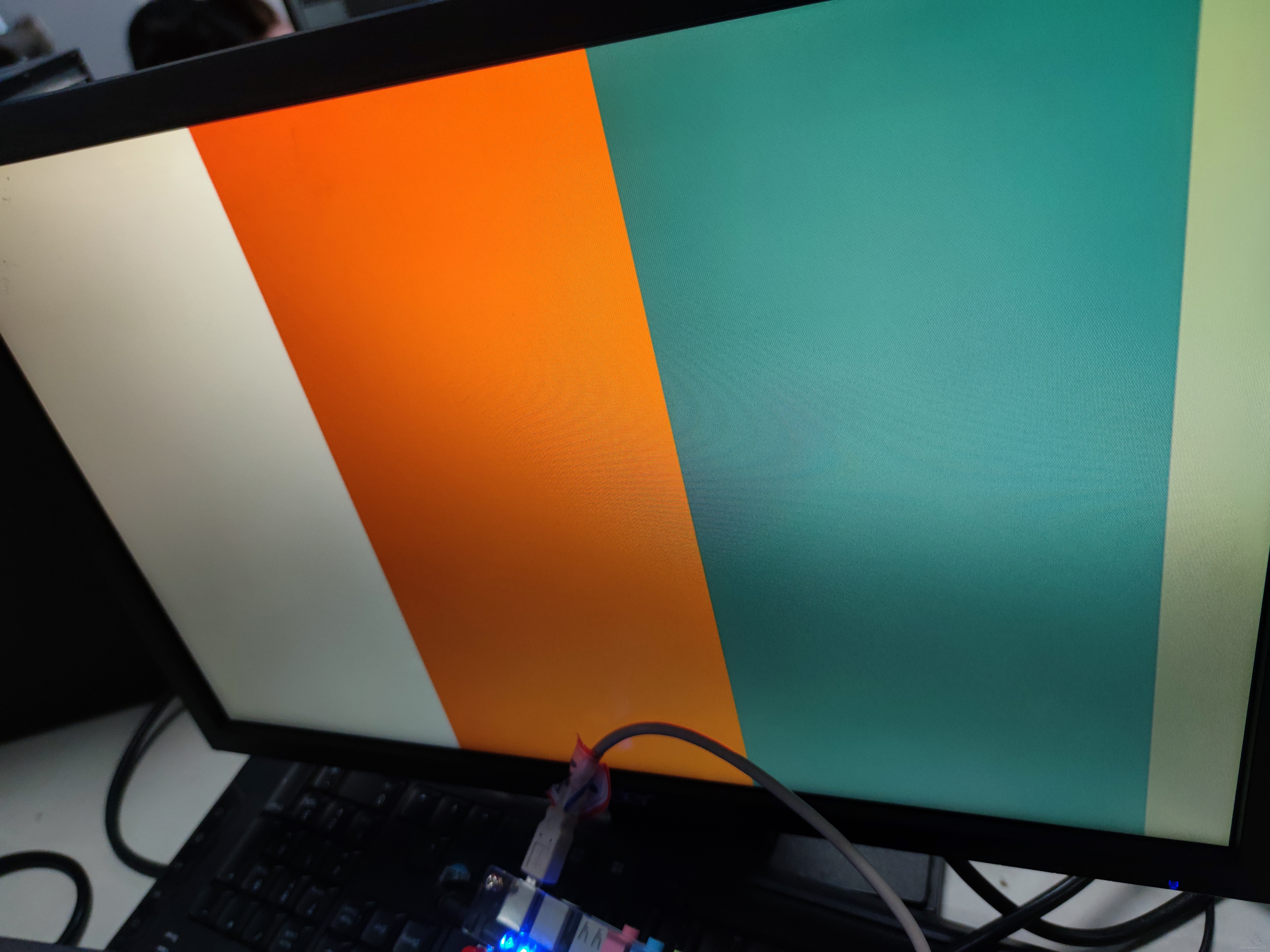
if(X>=0&&X<200)begin //X控制图像的横向显示边界:左边距屏幕左边144像素 右边界距屏幕左边界416像素
vga_rgb<=30'hffffffffff; //白色
end
else if(X>=200&&X<400)begin
vga_rgb<=30'hf00ff65f1f;
end
else if(X>=400&&X<600)begin
vga_rgb<=30'h9563486251;
end
else begin
vga_rgb<=30'h5864928654;
end
end
assign VGA_R=vga_rgb[23:16];
assign VGA_G=vga_rgb[15:8];
assign VGA_B=vga_rgb[7:0];
endmodule
In addition to the code, it is also necessary to configure the PLL IP core to set the clock, see below for details.
The running result is shown in the figure:
Five, VGA display color pictures
1. Image format hex
In the previous study, I learned that there are many image formats, such as JPEG, BMP, PNG, JPG, etc., and the number of bits of the image also includes monochrome, 16-color, 256-color, 4096-color, 16-bit true color, 24-bit true color , 32-bit true color Insert picture description here
These types.
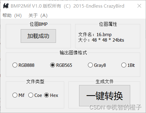
The format displayed by the VGA driver is RGB565. We first find a color picture that needs to be displayed, and after processing, convert the picture into a format that can be stored in the ROM. Then the VGA driver reads the data from the ROM and outputs it to the VGA display. screen display. Try to choose a small picture, because the ROM storage space is limited.
Use BMP2Mif software to convert bmp format pictures to hex files
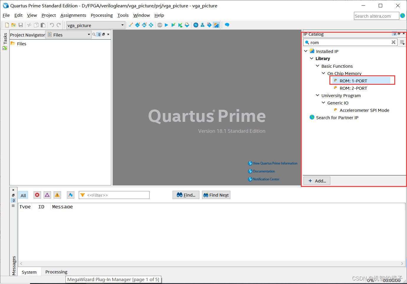
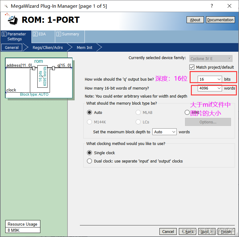
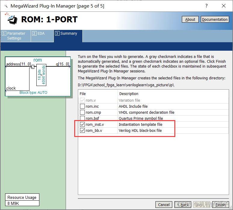
2. ROM IP core configuration
Create a new Quartus project, generate the ROM IP core, and save the generated mif file in the ROM Double-
click to select the ROM: 1-PORT
Uncheck q 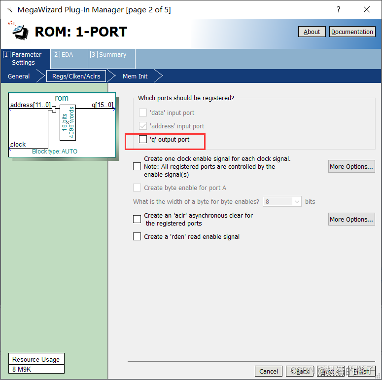
Load the HEX file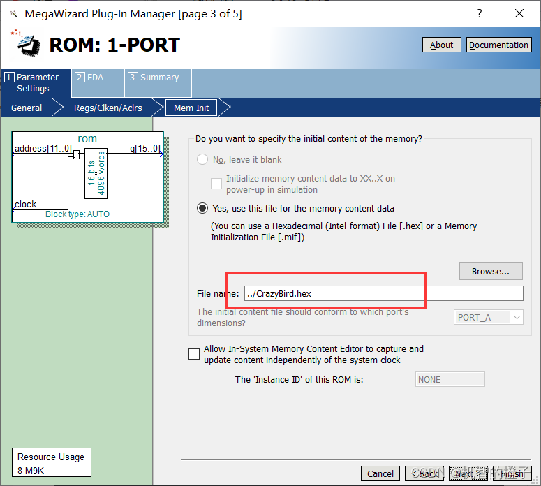
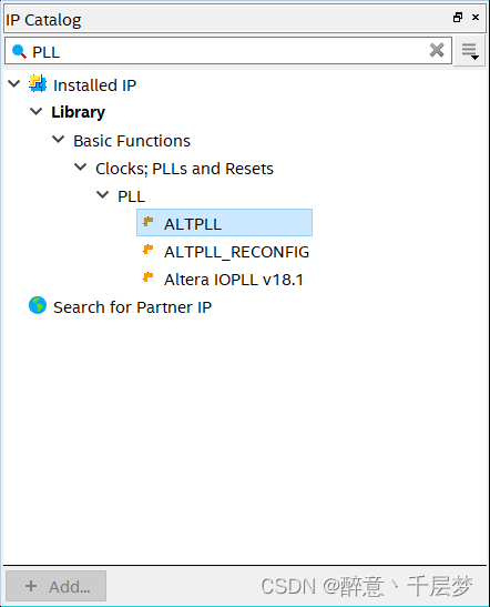
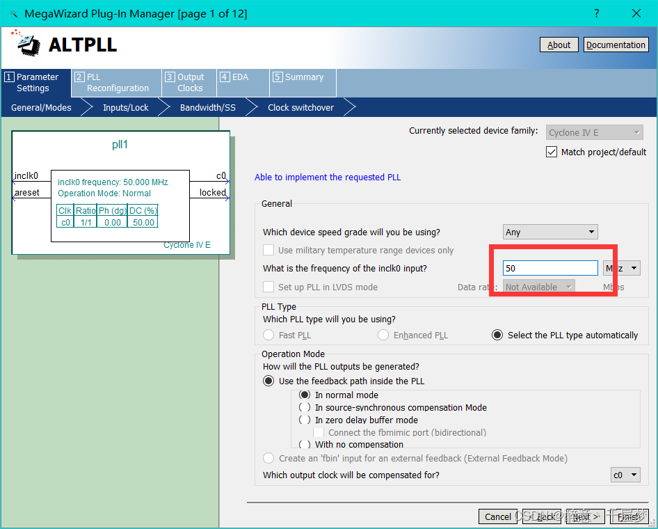
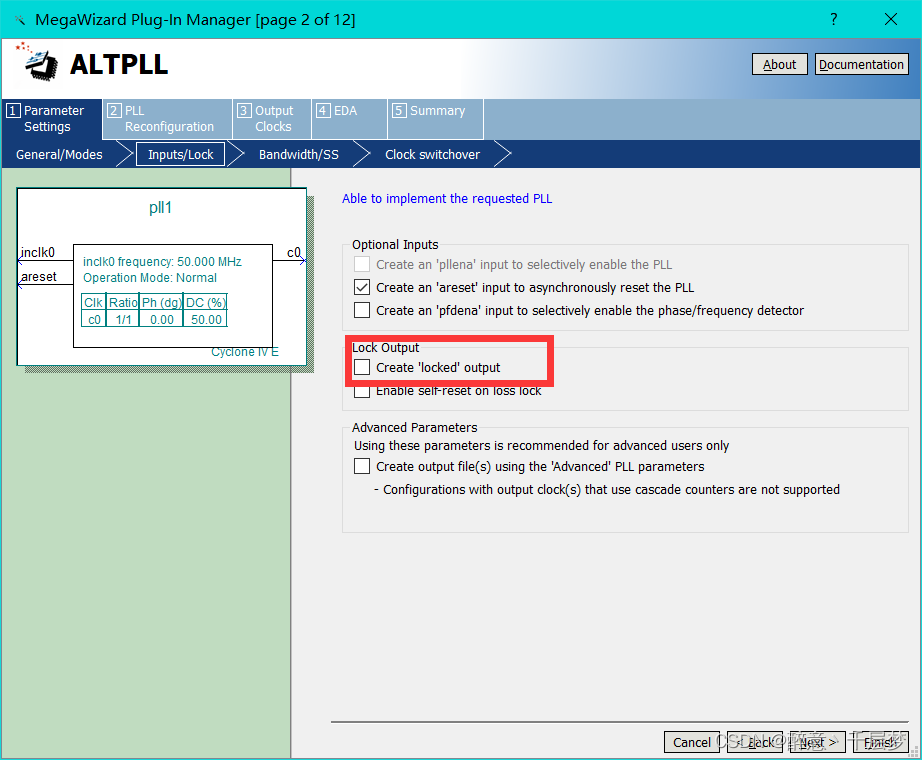
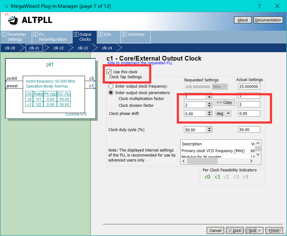
3. PLL IP core configuration
Use 640×480 60HZ and 800×600 72HZ respectively, the corresponding clocks are 25M and 50M respectively, need to use PLL for frequency division clock frequency = row frame length × column frame length * refresh rate, 640 × 480 60HZ corresponds to clock frequency = 800 × 525 × 60 = 25.2M Find the ALTPLL base clock
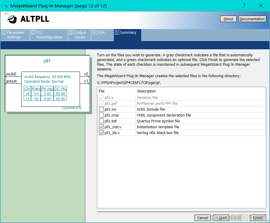
in the ip core, select 50M , uncheck the output enable c0, the default output is 50M, and the frequency of c1 is divided to 25M. If you need other clock frequencies, you can set it yourself. Check the following options and finish
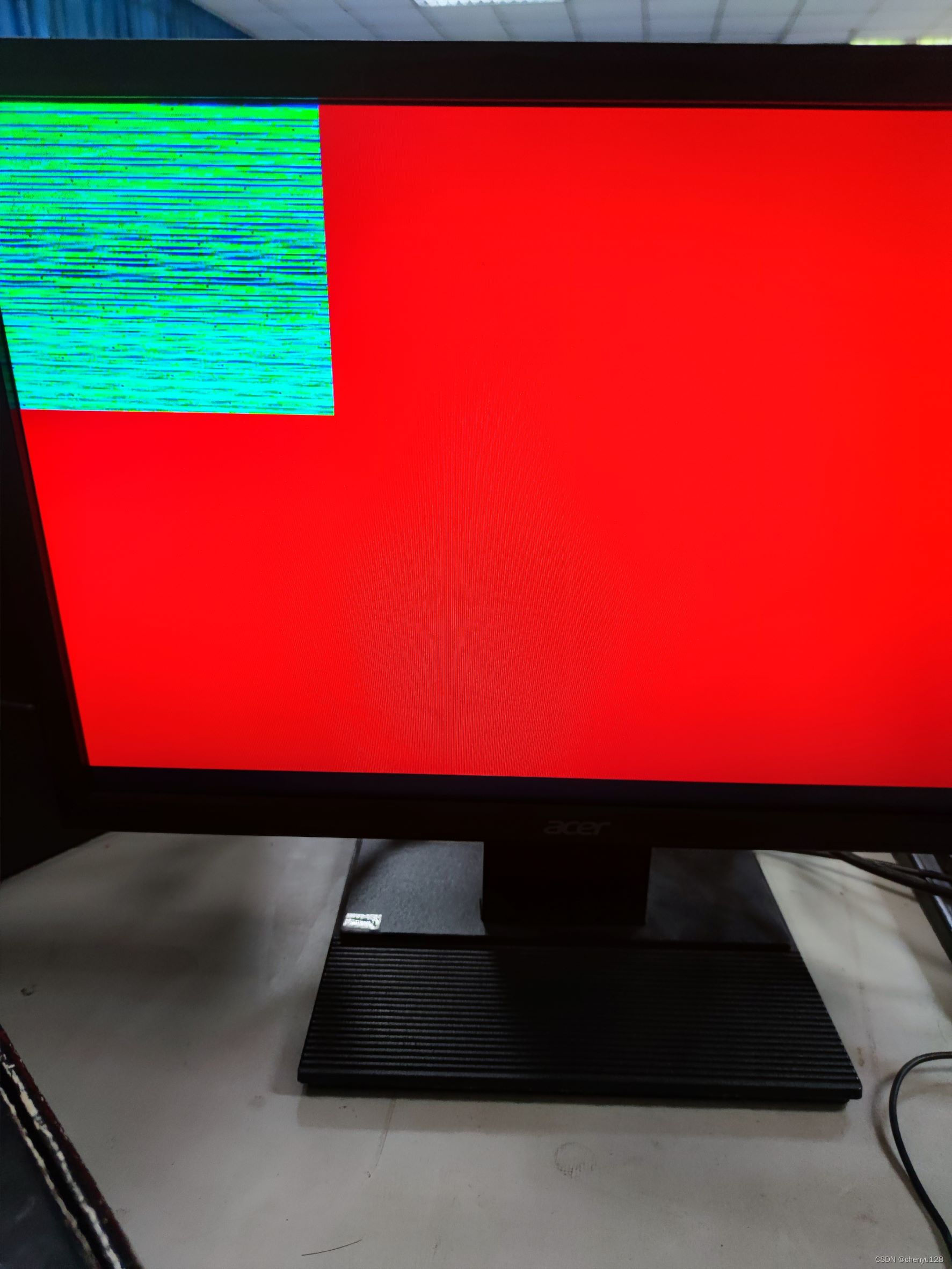
Result demonstration picture: (problem, unresolved)
6. Summary
VGA (Video Graphics Array) is a video transmission standard introduced by IBM together with PS/2 machine in 1987. It has the advantages of high resolution, fast display speed and rich colors, and has been widely used in the field of color displays. Does not support hot plugging, does not support audio transmission. For an FPGA engineer, especially a learner in the direction of video images, the VGA protocol must be mastered.
Through the study of the VGA protocol, I learned the display principle of VGA and the principle of image display on the computer. In my understanding, using FPGA to display pictures is like designing an image display chip. The purpose of using FPGA is to design a special chip that can be modified in the later stage. I hope that I can continue to work hard in the later study. The field of FPGA is extensive and profound.
7. Reference link
https://www.cnblogs.com/xianyuIC/p/11128817.html
https://blog.csdn.net/qq_45659777/article/details/124834294
https://blog.csdn.net/qq_47281915/article/details/125134764