vtkTubeFilter class
vtkTubeFilter is a filter that generates a tube around each input line. The tube consists of triangle strips and rotates around the tube as the line normal rotates. (Normals are calculated automatically if none exist.) The radius of the tube can be set to vary with a scalar or vector value. If the radius varies by a scalar value, the radius will be adjusted linearly. If the radius varies with the vector, use the mass flow rate to keep changing. If the radius varies by the norm of the vector, the radius will be adjusted linearly to its norm. You can also specify the number of sides for the tube. You can also specify which edges are visible. This is very useful for generating interesting banding effects. Additional options include the ability to cap tubes and generate texture coordinates. Texture coordinates can be used with associated texture maps to create interesting effects such as marking tubes with stripes corresponding to length or time.


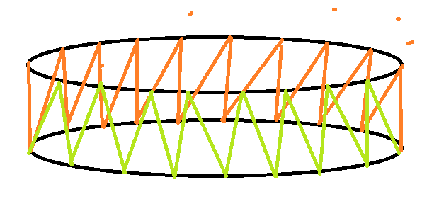
The points on the adjacent group of circles are connected one by one to form a triangular strip, which forms the side segment of the lumen;
This filter is often used to create thick or dramatic lines. Another common use is to combine this filter with vtkStreamTracer to generate stream pipes.
WARNING
The number of pipe sides must be greater than 3. Use vtkRibbonFilter if you want to use fewer edges (i.e. ribbons).
The input line must not have duplicate points, nor must it have normals at points parallel to the input/output line segment. (Duplicate points can be removed using vtkCleanPolyData.) If a line does not meet this criterion, the line will not be piped.
In the application of medical processing, a closed tube can be generated according to the curve drawn by the doctor, and the CT value or gray value of the voxel in the tube can be further counted.
example
Let's assume that we want to generate a lumen according to a curve, and then count the values in the lumen;
vtkNew<vtkNamedColors> colors;

double origin[3] = {

     0.0, 0.0, 0.0 };
double p0[3] = {

     1,0,0 };
double p1[3] = {

     1,1,0 };
double p2[3] = {

     1,1,1 };
double p3[3] = {

     0,-1,0 };

// Create a vtkPoints object and store the points in it
vtkNew<vtkPoints> points;
points->InsertNextPoint(origin);
points->InsertNextPoint(p0);
points->InsertNextPoint(p1);
points->InsertNextPoint(p2);
points->InsertNextPoint(p3);

vtkNew<vtkParametricSpline> spline;
spline->SetPoints(points);
vtkNew<vtkParametricFunctionSource> functionSource;
functionSource->SetParametricFunction(spline);
functionSource->Update();

vtkNew<vtkTubeFilter> Tube;
Tube->SetInputConnection(functionSource->GetOutputPort());
Tube->SetRadius(0.5);
Tube->SetNumberOfSides(20);
Tube->CappingOn();
Tube->SidesShareVerticesOn();
Tube->Update();
// Setup actor and mapper
vtkNew<vtkPolyDataMapper> mapper;
mapper->SetInputConnection(Tube->GetOutputPort());

vtkNew<vtkActor> actor;
actor->SetMapper(mapper);
actor->GetProperty()->SetColor(0, 1, 0);
// Setup render window, renderer, and interactor
vtkNew<vtkRenderer> renderer;
vtkNew<vtkRenderWindow> renderWindow;
renderWindow->AddRenderer(renderer);
vtkNew<vtkRenderWindowInteractor> renderWindowInteractor;
renderWindowInteractor->SetRenderWindow(renderWindow);
renderer->AddActor(actor);
renderer->SetBackground(colors->GetColor3d("Silver").GetData());

renderWindow->Render();
renderWindowInteractor->Start();
When the pipes generated in the code overlap:

Use CappingOnthe closed ends of the pipe: when set to
: the coordinates used before, the pipes do not overlap :SetRadius0.01

SetRadius0.5

double origin[3] = {

     0.0, 0.0, 0.0 };
double p0[3] = {

     0,3,2 };
double p1[3] = {

     5,4.4,3.6 };
double p2[3] = {

     10,4.4,4.2 };
double p3[3] = {

     15,4.4,4.8 };

According to the previous notes VTK notes-graphics related-polygon data conversion image data-vtkPolyData is converted to vtkImageData to convert the lumen to vtkImageDataMask data;
vtkNew<vtkNamedColors> colors;

double p0[3] = {

     0.0, 0.0, 0.0 };
double p1[3] = {

     1,0,0 };
double p2[3] = {

     1,1,0 };
double p3[3] = {

     1,1,1 };
double p4[3] = {

     0,-1,0 };

// Create a vtkPoints object and store the points in it
vtkNew<vtkPoints> points;
points->InsertNextPoint(p0);
points->InsertNextPoint(p1);
points->InsertNextPoint(p2);
points->InsertNextPoint(p3);
points->InsertNextPoint(p4);

vtkNew<vtkParametricSpline> spline;
spline->SetPoints(points);
vtkNew<vtkParametricFunctionSource> functionSource;
functionSource->SetParametricFunction(spline);
functionSource->Update();

vtkNew<vtkTubeFilter> Tube;
Tube->SetInputConnection(functionSource->GetOutputPort());
Tube->SetRadius(0.5);
Tube->SetNumberOfSides(20);
Tube->CappingOn();
Tube->SidesShareVerticesOn();
Tube->Update();
// Setup actor and mapper
vtkNew<vtkPolyDataMapper> mapper;
mapper->SetInputConnection(Tube->GetOutputPort());

auto pd = Tube->GetOutput();

vtkNew<vtkActor> actor;
actor->SetMapper(mapper);
actor->GetProperty()->SetColor(0, 1, 0);

vtkNew<vtkImageData> whiteImage;
double bounds[6];
pd->GetBounds(bounds);
double spacing[3]; // desired volume spacing
spacing[0] = 0.1;
spacing[1] = 0.1;
spacing[2] = 0.1;
whiteImage->SetSpacing(spacing);

// compute dimensions
int dim[3];
for (int i = 0; i < 3; i++) {


	dim[i] = static_cast<int>(ceil((bounds[i * 2 + 1] - bounds[i * 2]) / spacing[i]));
}
whiteImage->SetDimensions(dim);
whiteImage->SetExtent(0, dim[0] - 1, 0, dim[1] - 1, 0, dim[2] - 1);

double origin[3];
origin[0] = bounds[0] + spacing[0] / 2;
origin[1] = bounds[2] + spacing[1] / 2;
origin[2] = bounds[4] + spacing[2] / 2;
whiteImage->SetOrigin(origin);
whiteImage->AllocateScalars(VTK_UNSIGNED_CHAR, 1);

    unsigned char inval = 255;
    unsigned char outval = 0;
    vtkIdType count = whiteImage->GetNumberOfPoints();
    for (vtkIdType i = 0; i < count; ++i) {


        whiteImage->GetPointData()->GetScalars()->SetTuple1(i, i);
    }

    // polygonal data --> image stencil:
    vtkNew<vtkPolyDataToImageStencil> pol2stenc;
    pol2stenc->SetInputData(pd);
    pol2stenc->SetOutputOrigin(origin);
    pol2stenc->SetOutputSpacing(spacing);
    pol2stenc->SetOutputWholeExtent(whiteImage->GetExtent());
    pol2stenc->Update();

    // cut the corresponding white image and set the background:
    vtkNew<vtkImageStencil> imgstenc;
    imgstenc->SetInputData(whiteImage);
    imgstenc->SetStencilConnection(pol2stenc->GetOutputPort());
    imgstenc->ReverseStencilOff();
    imgstenc->SetBackgroundValue(outval);
    imgstenc->Update();

    vtkNew<vtkGPUVolumeRayCastMapper> gpuMapper;
    gpuMapper->SetInputData(imgstenc->GetOutput());
    gpuMapper->SetMaskTypeToBinary();
    gpuMapper->SetMaskInput(NULL);

    vtkPiecewiseFunction * psfunction = vtkPiecewiseFunction::New();

    //透明度传递函数
    psfunction->AddPoint(0.0, 0.0);
    psfunction->AddPoint(40.0, 0.0);
    psfunction->AddPoint(50.0, 0.3);
    psfunction->AddPoint(110.0, 0.4);
    psfunction->AddPoint(120, 0.5);
    psfunction->AddPoint(130, 0.6);
    psfunction->AddPoint(190, 0.8);
    psfunction->AddPoint(255, 1.0);

    vtkColorTransferFunction * colfunction = vtkColorTransferFunction::New();

    //颜色传递函数
    colfunction->AddRGBPoint(0.0, 0.5, 0.3, 0.2);
    colfunction->AddRGBPoint(50.0, 0.8, 0.5, 0.5);
    colfunction->AddRGBPoint(110.0, 0.6, 0.2, 0.3);
    colfunction->AddRGBPoint(190.0, 0.81, 0.27, 0.1);
    colfunction->AddRGBPoint(255.0, 0.5, 0.9, 0.9);

    vtkVolumeProperty * volpro = vtkVolumeProperty::New();

    //体数据属性
    volpro->SetColor(colfunction);
    volpro->SetScalarOpacity(psfunction);
    volpro->ShadeOn();
    volpro->SetInterpolationTypeToLinear();

    vtkVolume * data = vtkVolume::New();

    //体数据映射器和属性
    data->SetMapper(gpuMapper);
    data->SetProperty(volpro);

    // Setup render window, renderer, and interactor
    vtkNew<vtkRenderer> renderer;
    vtkNew<vtkRenderWindow> renderWindow;
    renderWindow->AddRenderer(renderer);
    vtkNew<vtkRenderWindowInteractor> renderWindowInteractor;
    renderWindowInteractor->SetRenderWindow(renderWindow);
    //renderer->AddActor(actor);
    renderer->AddVolume(data);
    renderer->SetBackground(0, 0, 0);
    renderer->ResetCameraClippingRange();
    renderer->SetBackground(colors->GetColor3d("Silver").GetData());

    renderWindow->Render();
    renderWindowInteractor->Initialize();
    renderWindowInteractor->Start();

After generation vtkImageData, the intersecting part of the line will be set as a non-polygon, this problem has not been found why;
