Article directory
1. Understand the digital tube
The digital tube can be divided into seven-segment digital tube and eight-segment digital tube according to the number of segments. The eight-segment digital tube has one more light-emitting diode unit than the seven-segment digital tube, that is, one more decimal point (DP). This decimal point can more accurately indicate what the digital tube wants. Display content; according to how many (8) can be displayed, it can be divided into 1-digit, 2-digit, 3-digit, 4-digit, 5-digit, 6-digit, 7-digit and other digital tubes.
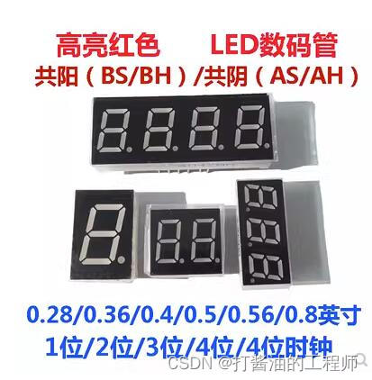
According to the connection method of the light-emitting diode unit, it can be divided into common anode digital tube and common cathode digital tube. A common anode digital tube refers to a digital tube in which the anodes of all light-emitting diodes are connected together to form a common anode (COM). When using a common anode digital tube, the common electrode COM should be connected to +5V. When the cathode of a certain field of light-emitting diodes is When it is low level, the corresponding field lights up. When the cathode of a certain field is high level, the corresponding field does not light up. Common cathode digital tube refers to a digital tube in which the cathodes of all light-emitting diodes are connected together to form a common cathode (COM). When using common cathode digital tubes, the common electrode COM should be connected to the ground wire GND. When a certain field of light-emitting diodes When the anode of a certain field is at a high level, the corresponding field lights up. When the anode of a certain field is at a low level, the corresponding field does not light up.
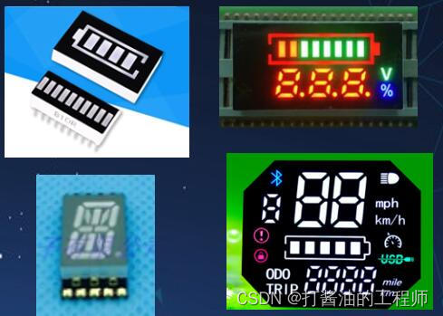
The inside of the digital tube is composed of multiple light-emitting diodes packaged together. They can have many colors, many shapes, and many styles, but essentially they all display by lighting up the internal LEDs. As long as the panel is well-made Yes, theoretically it can display any characters or patterns.
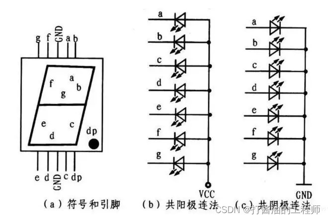
According to the connection method of the light-emitting diode unit, it can be divided into common anode digital tube and common cathode digital tube. The suffix A means common anode and K means common cathode
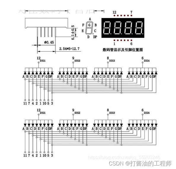
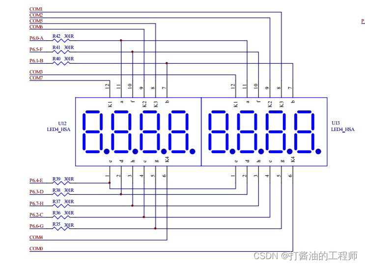
4-digit digital tube:
2. Control principle
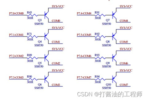
In this section, we first light up the last "8". According to the schematic diagram, only P6 and com0 (P7.0) are needed.
Create a new excel analysis:
binary, decimal, hexadecimal and corresponding relationships are displayed respectively.
Please refer to: Conversion between hexadecimal systems (super detailed) .
Convert decimal to arbitrary base
The methods are all similar. The essence is to use the remainder method. If it is converted to binary, it is to find the remainder of 2. If it is converted to octal, it is to find the remainder of 8. And so on, until the quotient is 0, and the remainder is taken in reverse (sort the results from bottom to top).
Convert other bases to decimal
The method of multiplying the base by the exponent n times. Base: the base value itself (for example, the binary number 1010, 1010 is the base), exponent: the corresponding base value (the binary exponent is: 2, the octal exponent is: 8), n: represents the position of the base, divided by decimal points , the number on the left starts counting from 0, and the number on the right (that is, the number after the decimal point) starts counting from -1.
3. The digital tube realizes the display of 0-9
1. Use an array to define the internal code of 0-9
Use the "3. Button control LED" project as a template to create a new "5. Digital tube".
Define the digital tube display array:
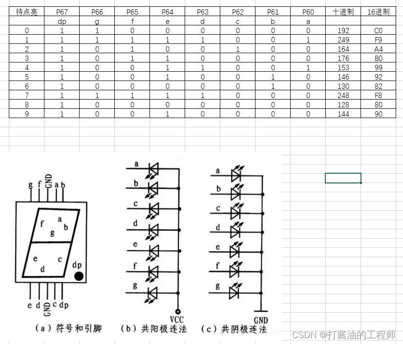
u8 SEG_Tab[10] = {0xc0,0xf9,0xa4,0xb0,0x99,0x92,0x82,0xf8,0x80,0x90}; //0-9
The difference between segment code and bit code
Segment refers to abcdefg dp and other LEDs. The segment code refers to which stroke to choose, and the bit code refers to which 8th to choose.
2. Try to use delay to achieve a cyclic display of 0-9
Use an array to display 0 to 9. The array index can use variables. Here u8 num is defined.
The main() function is modified as follows:
void main()   //程序开始运行
{
	u8 num = 0;
	sys_init();
	usb_init();	//初始化USB代码
	EA = 1;


    while(1) //死循环
    {
		if( DeviceState != DEVSTATE_CONFIGURED ) 	//判断USB是否连接成功,最新版usb.h中该有定义
			continue;
		if( bUsbOutReady )    //判断有没有接收到数据
		{
			usb_OUT_done(); //接收应答(固定格式)
		}
		P70 = 0;			//开启一个数码管
//---------------------------
		P6 = SEG_Tab[num];	//这个数码管输出段码
		num++;
		if(num>9)
			num = 0;
		delay_ms(1000);
	}
}
Realized the cycle of digital tube 0-9.
3. Use the buttons to control the addition or subtraction of numbers.
Adjust the while main loop code to implement key addition and subtraction:
    while(1) //死循环
    {
		if( DeviceState != DEVSTATE_CONFIGURED ) 	//判断USB是否连接成功,最新版usb.h中该有定义
			continue;
		if( bUsbOutReady )    //判断有没有接收到数据
		{
			usb_OUT_done(); //接收应答(固定格式)
		}
		P70 = 0;			//开启一个数码管
---------------------------
//		P6 = SEG_Tab[num];	//这个数码管输出段码
//		num++;
//		if(num>9)
//			num = 0;
//		delay_ms(1000);
		P6 = SEG_Tab[num];	//这个数码管输出段码

		if (KEY1 == 0)
		{
			delay_ms(10);
			if (KEY1 == 0)
			{
				while(KEY1 == 0); //松开后继续执行以下程序
				if(num<9)
					num++;

			}
		}
		if (KEY2 == 0)
		{
			delay_ms(10);
			if (KEY2 == 0)
			{
				while(KEY2 == 0);
				if(num>0)
					num--;

			}
		}

	}
Feeling a bit monotonous, add a buzzer:
if (KEY2 == 0)
			{
				BEEP = 0;
				delay_ms(10);
				BEEP = 1;
				while(KEY2 == 0);
				if(num>0)
					num--;

			}
First beep once, then release the button to add or subtract.
Summarize
1. Understand the origin of the digital internal code of the digital tube
2. Learn how to obtain values from the digital tube through arrays
Homework:
1. Try to use a digital tube to display letters or symbols such as HJLN o PU tr.
2. Use a button to set the digital tube to display the numbers 0-9 in a cycle. When pressing another button, the buzzer will sound as many times as the number displayed on the digital tube.