1. Introduction to Linux audio
1. History of Linux audio
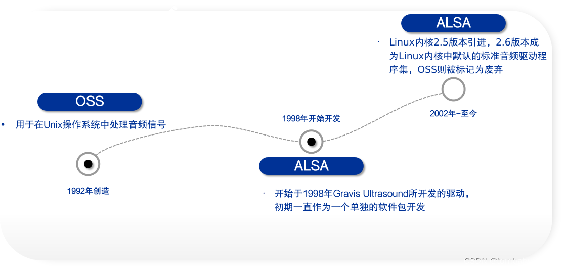
Initially, the OSS framework was launched in 1992 for processing audio signals in Unix operating systems. Until the ALSA driver developed by Gravis Ultrasound in 1998, ALSA had been developed as a separate software package, and the OSS framework had been used by the LINUX kernel. Until 2002, when Linux kernel version 2.5 was introduced, version 2.6 became the default standard audio driver set in the Linux kernel, and OSS was marked as obsolete.
2. Frequently Asked Questions about Linux Audio
- Audio input and output device missing
- Audio input and output unresponsive
- Headphone mic unresponsive
- Audio input noise
2. Linux audio framework
First, let’s take a look at the mainstream audio framework currently used in Linux audio, which is ALSA.
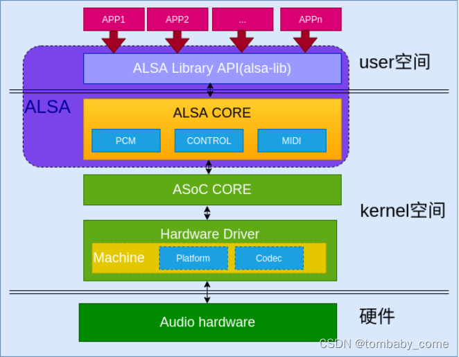
1. ALSA (Advanced Linux Sound Architecture, advanced Linux audio architecture)
- Alsa application: It is an upper-level debugging tool provided in alsa alsa-tools. Users can directly transplant it to the platform they need. These applications can be used to implement playback, capture, controls, etc., such as aplay, a common debugging tool for sound card problems. arecord, amixer, etc.
- Alsa library API: alsa user library interface, commonly known as alsa-lib. (The applications in alsa-tools are implemented based on the API provided by alsa-lib)
- Alsa core: alsa core layer, provides logical device (pcm/ctl/midi/timer/..) system calls upwards, and drives hardware devices (Machine/i2s/dma/codec) downwards
2、PCM
PCM is a technology that converts sound from analog signals (signals that can be recognized by the human ear) to digital signals. It uses a fixed frequency to sample the analog signal, processes the signal after sampling, and converts the processed signal data Output or record to a storage medium, thereby producing digital audio.
- AC97: Usually used for PC sound cards, it is a 5-wire interface. Each AC97 frame is 21uS long and is divided into 13 time slots.
- BCLK: driven by AC97, 12.288 MHz
- SYNC: Synchronization signal, driven by Controller, is 48 kHz
- SDATDIN: used for capture, AC97->Controler
- SDATAOUT: used for playback, Controler->AC97
- RESET: generated by Controller, used to wake up AC97
I2S is a 4-wire DAI commonly used in HiFi, STB and portable devices
- SCLK: serial clock
- LRCK: also called WS, channel selection line
- Tx: used to transmit audio data
- Rx: used to receive audio data
PCM is another 4-wire interface, very similar to I2S, and can support more flexible protocols
- BCLK: bit clock, varies according to sampling rate
- SYNC: synchronization signal
- Tx: used to transmit audio data
- Rx: used to receive audio data
3、CONTROL
The Control interface mainly allows user space applications to access and control multi-way switches, sliding controls, etc. in the audio codec chip for volume control, muting, etc.
4、MIDI
It is a serial interface for connecting synthesizers, keyboards, props, and lighting controllers on the stage.
5、ASOC
Problems with ALSA:
- The Codec driver is severely coupled with the SOC interrupt CPU, which will lead to code duplication. A Codec driver will have different versions on each CPU.
- There is no standard way to notify the user when an audio event occurs (plugging or unplugging headphones, speakers), especially on mobile devices. This event is very common.
- When playing/recording audio, the driver will keep the entire codec powered on, which will waste a lot of power on the mobile terminal. At the same time, it does not support changing the sampling frequency/configuring current to save power consumption.
In response to the above problems, ASOC was proposed to try to solve the above problems. The solution is as follows:
- Codec code is independent and no longer coupled to the CPU, which can increase codec code reuse.
- The Codec and Soc communicate through a simple I2S/PCM audio interface, so that the SOC and Codec only need to register their relevant interfaces to the ASOC code.
- Dynamic Power Management (Dynamic Audio Power Management)DAPM. DAPM always automatically sets the Codec to run in the lowest power consumption state.
- Eliminate the pop sound. Control the order in which each widget is powered on and off to eliminate the pop sound.
- Add platform-related controls and run the platform to add control devices to the sound card
6、Machine
Machine can be understood as a bridge, used to establish a connection between Codec and Platform. This Machine specifies which Platform and Codec the machine uses, and the connection between the two will eventually be established through Machine.
7、Platform
It can be understood as a certain SOC platform. The platform driver includes audio DMA engine driver, digital interface driver (I2S, AC97, PCM) and any audio DSP driver related to the platform. Similarly, this Platform can also be reused and can be directly reused in different Machines.
8、Codec
Codec is the driver of the codec chip. This Codec driver is platform-independent and includes functions such as: audio control interface, audio read and write IO interface, and DAPM definition, etc.
3. HDA of Linux audio
HDA (High Definition Audio, high-definition sound technology)
- The sound effect technology proposed by Intel in 2004 can display high-definition sound quality and can perform multi-channel playback, surpassing other integrated sound codecs in the past, such as Audio Codec 97, in terms of sound quality.
- Currently HDA technology has been widely adopted by major chip manufacturers, such as Intel, Realtek, various HDMI and conexant, etc. all use this technology. In addition to repairs by realtek, Intel and other manufacturers, we external tasks can currently repair audio problems. Most of the content is also under ALSA's pci/hda framework.
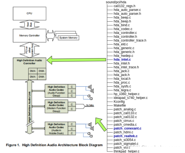
- High Definition Audio Controller: is a bus-mastered I/O peripheral that connects to system memory through PCI or other typical PC peripheral connection host interfaces. It contains one or more DMA engines, each of which can be set up to transfer a single audio "stream" from the codec to memory, or from memory to the codec, depending on the DMA type.
- High Definition Audio Link: High Definition Audio Controller is physically connected to one or more codecs through High Definition Audio Link.
- High Definition Audio Codec: One or more Codecs are connected to the link. Codec extracts one or more audio streams from the time multiplexed link protocol and converts them into output streams through one or more converters (labeled "C").
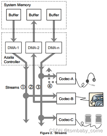
Each activated Stream must be connected to a DMA engine, and the DMA type is determined by the device type.
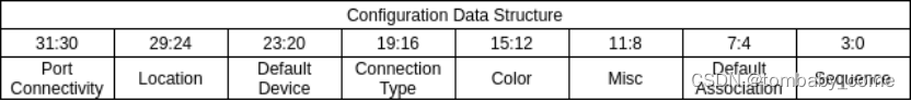
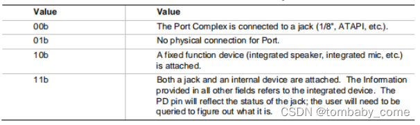
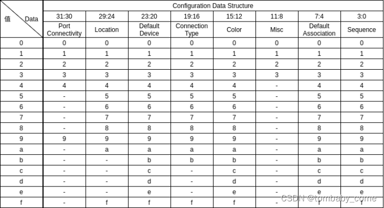
- Port Connectivity: Indicates the external connectivity of the Pin Complex. Software can use this value to learn which pin complexes are connected to the jack, to internal devices, or not connected at all.
- Location: Indicates the physical location of the connected jack or device. For example, this device is connected to the "front panel headphone jack" and not the rear panel jack.
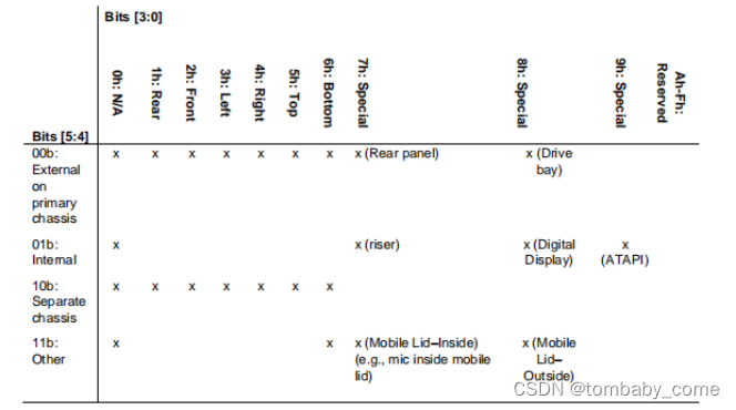
- The position field is divided into two parts, high bits [5:4] and low bits [3:0]. High bits [5:4] provide the overall location, e.g. "external" (on the main system chassis, accessible to the user), "internal" (on the motherboard, inaccessible without opening the box), on a separate chassis (like a mobile case) )or others.
- The low bits [3:0] provide geometric position, such as "front", "left", etc., or provide special encoding to indicate position, such as a microphone mounted on a moving cover. The "x" in the table on the left indicates the combinations the software should support. While all combinations are allowed, not all are possible or expected.
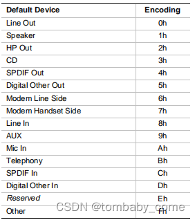
- Default Device: Indicates the intended use of the jack or device. This can indicate a label on the jack or a device hardwired to the port, such as an integrated speaker, etc.
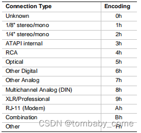
- Connection Type: Indicates the type of physical connection, such as a 1/8-inch stereo jack or optical digital connector, etc. Software can use this information to provide a useful user interface description to the user, or to modify the reported codec capabilities based on the device's capabilities for physical transmission outside the codec.
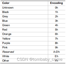
- Color: Indicates the color of the physical jack used by the software.
- Misc: is a bit field that indicates additional information about the jack. Currently, only bit 0 is defined. If bit 0 is set, it indicates that the jack does not have presence detection, so even though the Pin Complex indicates that the codec hardware supports presence detection on this jack, external circuitry cannot support the feature.
- Default Association: The software uses Default Association and Sequence together to combine pin complexes (and jacks) into functional blocks to support multi-channel operation. For resources such as processing nodes or input and output converters, lower default affinity values will have higher priority.
- Sequence: Sequence represents the order of jacks in the associated group. The lowest numbered jack in the associated group should be assigned the lowest numbered channel in the stream, etc. The numbers do not have to be consecutive within the group, only the order is important. Serial numbers must be unique within a set of default associations.
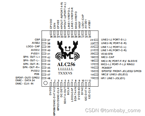
The configuration pin register needs to be configured in detail according to the Pin Assignments and Pin Descriptions in the datasheet of the sound card chip. For example ALC256:
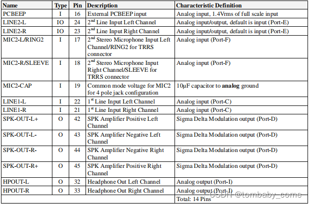
The configuration pin register can fix problems such as the system having no input and output devices, not recognizing headphones when plugged in, headphones/microphones unable to record, and headphone/speaker output unresponsive. But the noise problem is difficult or rarely solved by configuring Pin.
4. Configuration of audio codec in Linux
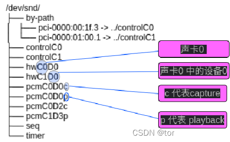
In Linux, the system's /dev/snd/ directory records the device files of the audio devices currently being used by the system, as follows:
In HDA implementation, the system configuration interface is reserved in the system, namely /sys/class/sound/hwCxDy, as follows:
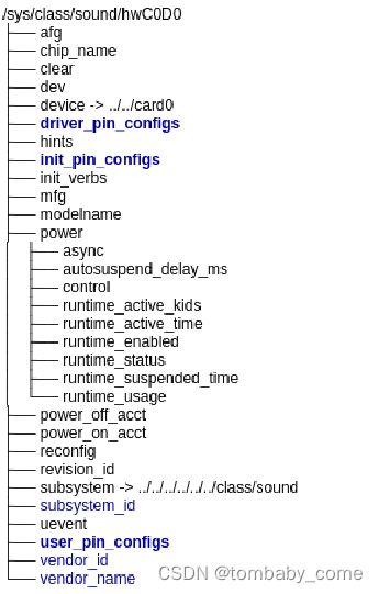
For descriptions of each interface, please refer to the following table:
| serial number |
interface |
illustrate |
| 1 |
name |
The name of the codec can be modified directly by writing a new string. |
| 2 |
init_verbs |
verbs that need to be executed additionally during initialization. Add the required verbs to this file, which can be found in Executed during initialization. |
| 3 |
hints |
Hints to the codec, for example, writing jack_detect = no will disable the codec's jack dectection function. |
| 4 |
init_pin_configs |
Record the initial pin default config of the BIOS settings. |
| 5 |
driver_pin_configs |
Record the part where the codec modified the pin default config value. |
| 6 |
usr_pin_configs |
Writing your own configuration can overwrite the settings set during BIOS startup. |
| 7 |
reconfig |
Trigger codec reconfiguration. Once any value is written to this file, the driver will re-initialize the codec tree again. |
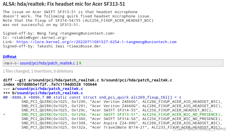
Most of the fixes in our audio are to modify the driver_pin_configs configuration to make the audio devices equipped on our machines perform better. For example, the following fix submission configures the driver_pin_configs value to 0x18, 0x01a110f0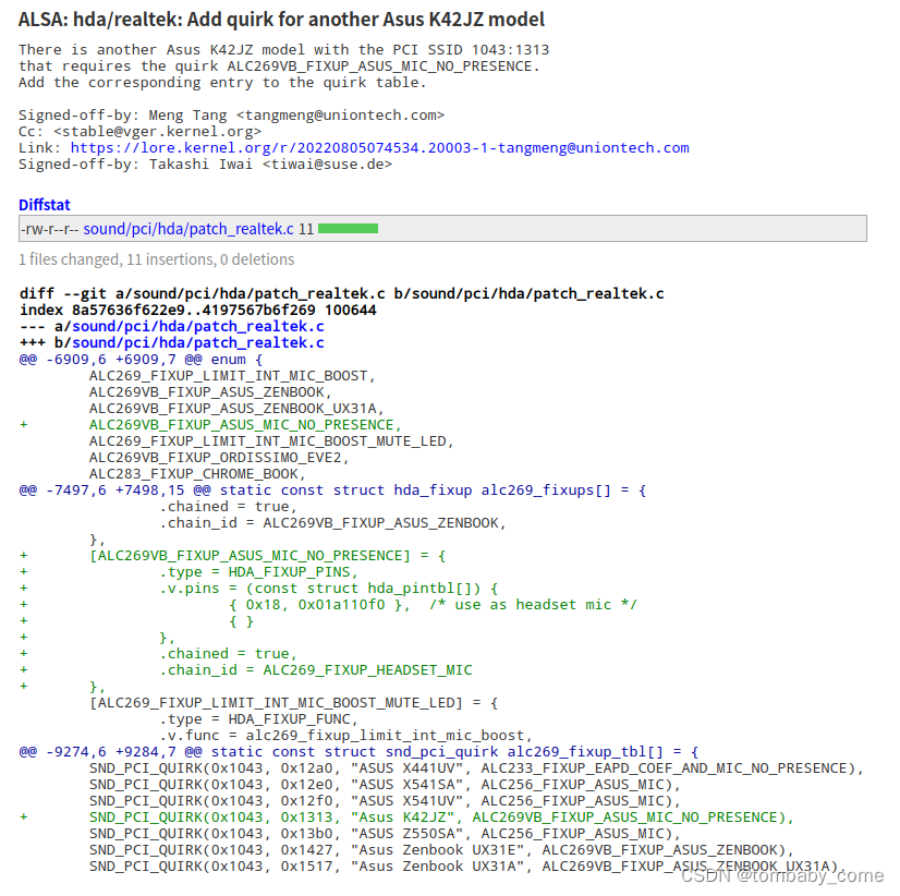
There are two main ways to configure this patch:
1. Confirm the sound card model of your current machine and see if it has been repaired according to the current community mainline code, or whether there are configuration modifications for the same machine or chip model. If so, we can try to see if the existing configuration program is there. It also performs well in our environment. The following example uses the existing repair configuration to repair the audio problem of the local machine:
2. When the sound card equipped on your machine has been repaired in the current community mainline code, or the configuration of the same machine or chip model has been modified, and the existing configuration program we tried did not perform well in our environment, then we have to Configure the fix program yourself for the sound card of your local machine.
How to configure it needs to be configured in accordance with the HDA configuration instructions mentioned in Chapter 3. We can use the hdajackretask command provided by alsa-tools-gui to visually verify the configuration modification.
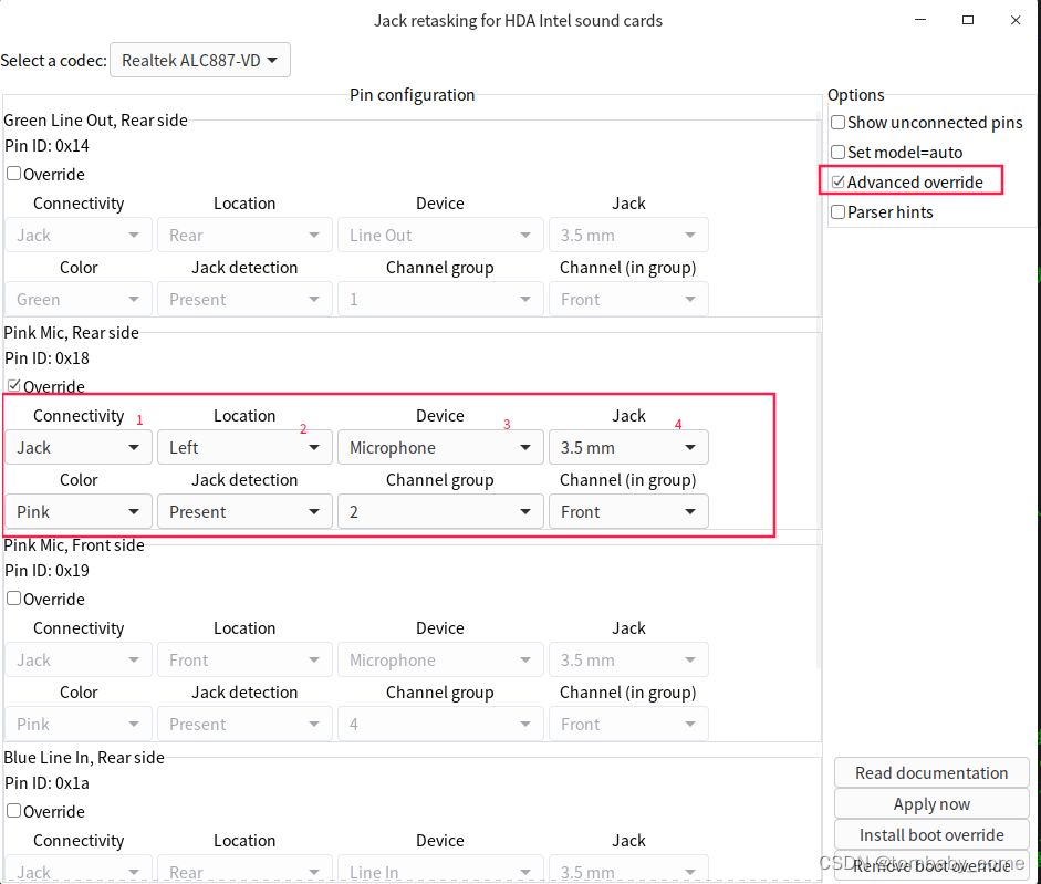
Until we find a configuration that can be used, the root HDA configuration item is finally written to driver_pin_configs.
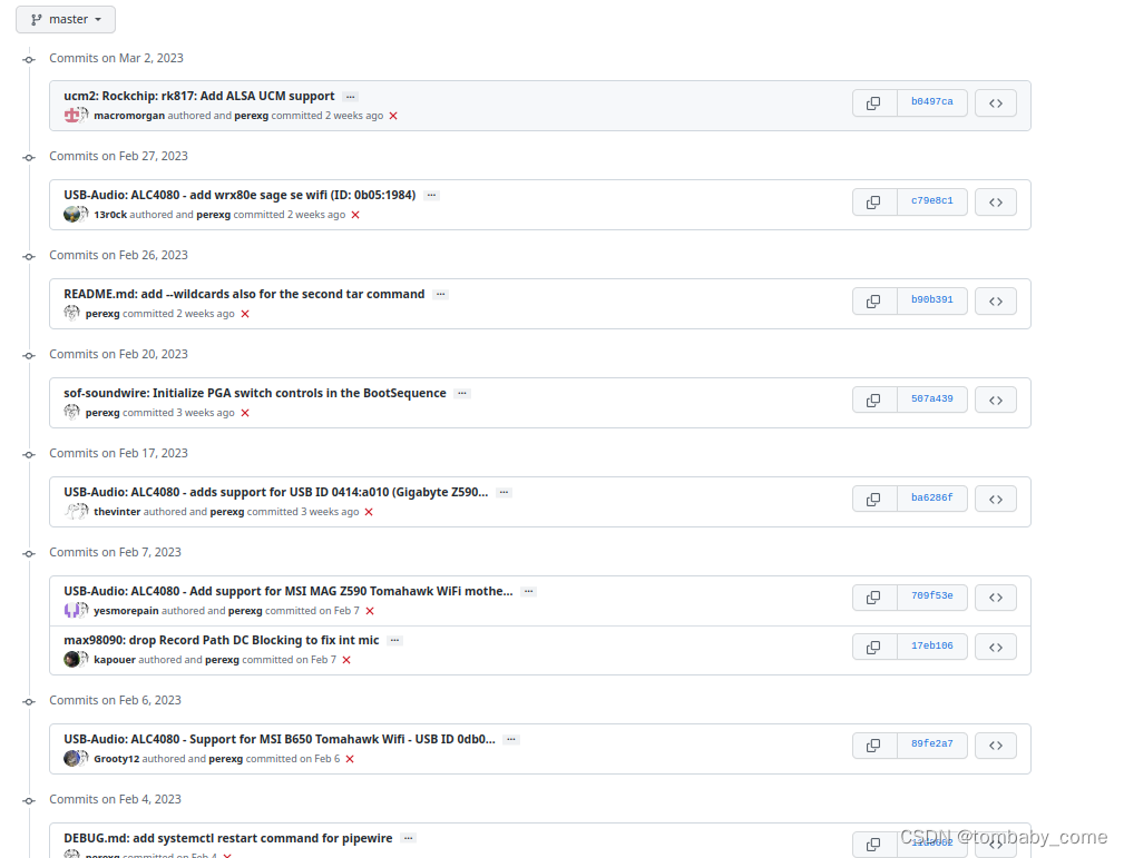
3. In addition, the system layer can also be configured, which ultimately affects the configuration of usr_pin_configs and has a higher priority than init_pin_configs and driver_pin_configs. The alsa-ucm-conf package currently launched and continuously optimized by alsa is also focused on optimizing audio configuration at the system level.
Currently GitHub - alsa-project/alsa-ucm-conf: ALSA Use Case Manager configuration This community is also very active. It uses json syntax to configure the configuration of related audio devices. If you are interested, you can study it.
5. Linux audio noise
In addition to fatal problems that directly affect use such as missing audio input and output devices, unresponsive audio input and output, and unresponsive headphone mics, audio input noise problems are also very common. However, audio noise problems are often caused by either hardware or environmental effects, or Even if it can be repaired through software optimization, it is difficult for ordinary developers to repair it without understanding the core design of the sound card chip and the circuit conditions of the motherboard. Let us understand below the main manifestations and possible causes of noise problems:
1. Hum: the so-called transformer sound, with complex sources
- Device process design is unreasonable
- Insufficient shielding of connecting cables
- The internal circuit is not working properly due to low power supply voltage.
2.Puff: the so-called spark sound
- Too much dust accumulates inside the device
- Component wear and tear, exceeding service life
3. The sound of running water: high-frequency self-excitation phenomenon
- Poor circuit design is a quality problem
4. Howling and steamboat sounds: low-frequency self-excitation phenomenon
- Turn off the power and check whether the connectivity between the components is intact
5. Occasional noise: crosstalk from AC power supply lines
6. Broadcasting sound: It is easy to cause high-frequency self-excitation, and in severe cases, the speaker or earphones may be burned out.
- Poor circuit design
- The amplifier has a poor open-loop frequency response
- Severe nonlinear distortion
- Not properly handled
The most common audio noise problem is current noise. In addition to the design flaws of the hardware itself, the current noise problem is usually caused by the audio filter not handling the frequency range of the audio input well, resulting in some sound being picked up or amplified that should not be picked up or amplified. Caused by the input or amplification of audio signals, and current processing often requires a filter to adjust the pickup frequency range to analyze the modulation (this requires familiarity with the filter principle and the sound card chip circuit diagram, which is a new field for kernel developers) and debugging methods, so such problems are often difficult to solve)