1. The basic functions required for the task
When the power is turned off, the white light is on and the blue light is off. At this time, there is no response when pressing the button for a long time. When the brightness of the white light is reduced, the blue light remains off. Click the button once, the white light goes out, and the blue light turns on. At this time, the light controlled by the W pin turns on. Keep clicking keys. The blue light is on. At this time, the light controlled by the W pin goes out, and the light controlled by the Y pin changes from off to on. Short press the W pin again, the light controlled by the Y pin and the blue light will light up together. In the power-on state, you can control the brightness of the light controlled by the W pin and Y pin by long pressing the button.
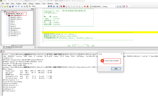
2. Why does Device Type not Match always appear during emulation? Please refer to the documentation for the reason. The reason is that the selected chip does not match the connected emulator.
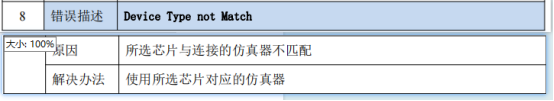
Software error reporting interface
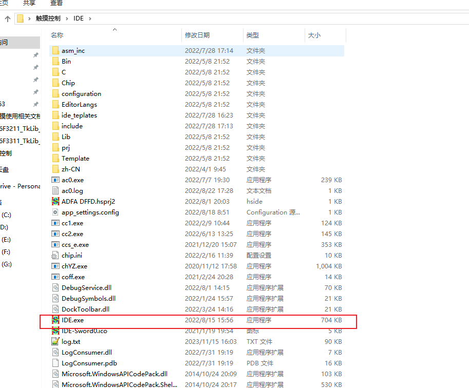
Solution, use other versions of IDE
3. Current planning ideas
Assume that during hardware processing, when a button is touched, an event occurs. At this time, it is necessary to detect whether this event occurs in a loop all the time. If it occurs, then execute the program to control the blue and white lights.
The first difficulty is how to distinguish between long press and tap
The current idea is that multiple key press events triggered in a short period of time are considered long presses, and other events that have not reached this number are considered short presses.
The second difficulty is to execute different logic code segments according to the long press or short press of the microcontroller, such as controlling the status switching of the light or controlling the corresponding change of light brightness.
The current idea is to use a state machine or switch case statement to switch states. As for controlling the brightness change of the light, the PWM duty cycle is calculated in proportion to the number of events. Another idea is to use a timer to judge. If the flag bit indicating that a long press event is occurring is 1, the PWM duty cycle can be set appropriately, so that the length of time for the zero degree of the control light to reach the minimum or maximum brightness can be achieved. .
4. Current doubts
1. How to observe debugging information. For example, other microcontrollers can use the serial port to print debugging information. So where and how can the printed information of this online simulation be obtained?
2. Implement the corresponding functions on the simulation board and then burn them into the sample board. Doesn't this require changing the pins? Why not just use the sample board to simulate it?
3. If the LED light of the patch is not observed on the simulation board, do I need to solder it myself?