https://alsa-project.org/main/index.php/DAPM
https://www.kernel.org/doc/html/v4.11/sound/soc/dapm.html
There are 4 power domains within DAPM:
- Codec domain – VREF, VMID (core codec and audio power). Usually controlled at codec probe/remove and suspend/resume, although can be set at stream time if power is not needed for sidetone, etc.
- Platform/Machine domain – physically connected inputs and outputs. Is platform/machine and user action specific, is configured by the machine driver and responds to asynchronous events. e.g when HP are inserted
- Path domain – audio subsystem signal paths. Automatically set when mixer and mux settings are changed by the user. e.g. alsamixer, amixer.
- Stream domain – DAC's and ADC's. Enabled and disabled when stream playback/capture is started and stopped respectively. e.g. aplay, arecord.
Codec/DSP Widget Interconnections
Widgets are connected to each other within the codec, platform and machine by audio paths (called interconnections). Each interconnection must be defined in order to create a map of all audio paths between widgets.
This is easiest with a diagram of the codec or DSP (and schematic of the machine audio system), as it requires joining widgets together via their audio signal paths.
Map Hardware to Widget (TLV320AIC23)
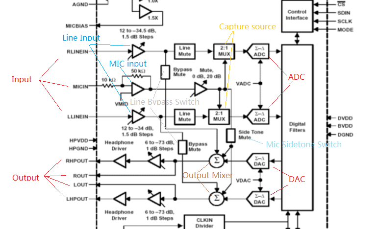
capture signal path:
LLININ->Line Input->Catpture source ->ADC
MICIN->Mic Input->Catpute source->ADC
playback signal path:
DAC->Ouptput Mixer->LOUT/LHPOUT/ROUT/RHPOUT
LLININ->Line Input->Output Mixer->LOUT
MICIN->Mic Input ->Output Mixer->LOUT/LHPOUT/ROUT/RHPOUT
DAPM Widgets:
static const struct snd_soc_dapm_widget tlv320aic23_dapm_widgets[] = {
    SND_SOC_DAPM_DAC("DAC", "Playback", TLV320AIC23_PWR, 3, 1),
    SND_SOC_DAPM_ADC("ADC", "Capture", TLV320AIC23_PWR, 2, 1),
    SND_SOC_DAPM_MUX("Capture Source", SND_SOC_NOPM, 0, 0,
             &tlv320aic23_rec_src_mux_controls),
    SND_SOC_DAPM_MIXER("Output Mixer", TLV320AIC23_PWR, 4, 1,
               &tlv320aic23_output_mixer_controls[0],
               ARRAY_SIZE(tlv320aic23_output_mixer_controls)),
    SND_SOC_DAPM_PGA("Line Input", TLV320AIC23_PWR, 0, 1, NULL, 0),
    SND_SOC_DAPM_PGA("Mic Input", TLV320AIC23_PWR, 1, 1, NULL, 0),

    SND_SOC_DAPM_OUTPUT("LHPOUT"),
    SND_SOC_DAPM_OUTPUT("RHPOUT"),
    SND_SOC_DAPM_OUTPUT("LOUT"),
    SND_SOC_DAPM_OUTPUT("ROUT"),

    SND_SOC_DAPM_INPUT("LLINEIN"),
    SND_SOC_DAPM_INPUT("RLINEIN"),

    SND_SOC_DAPM_INPUT("MICIN"),
};
DAPM routes:
static const struct snd_soc_dapm_route tlv320aic23_intercon[] = {
    /* Output Mixer */
    {"Output Mixer", "Line Bypass Switch", "Line Input"},
    {"Output Mixer", "Playback Switch", "DAC"},
    {"Output Mixer", "Mic Sidetone Switch", "Mic Input"},

    /* Outputs */
    {"RHPOUT", NULL, "Output Mixer"},
    {"LHPOUT", NULL, "Output Mixer"},
    {"LOUT", NULL, "Output Mixer"},
    {"ROUT", NULL, "Output Mixer"},

    /* Inputs */
    {"Line Input", "NULL", "LLINEIN"},
    {"Line Input", "NULL", "RLINEIN"},

    {"Mic Input", "NULL", "MICIN"},

    /* input mux */
    {"Capture Source", "Line", "Line Input"},
    {"Capture Source", "Mic", "Mic Input"},
    {"ADC", NULL, "Capture Source"},

};
Each input in this example has a kcontrol associated with it (defined in example above) and is connected to the output mixer via its kcontrol name. We can now connect the destination widget (wrt audio signal) with its source widgets.
/* PGA Mixer controls for Line and Mic switch */
static const struct snd_kcontrol_new tlv320aic23_output_mixer_controls[] = {
    SOC_DAPM_SINGLE("Line Bypass Switch", TLV320AIC23_ANLG, 3, 1, 0),
    SOC_DAPM_SINGLE("Mic Sidetone Switch", TLV320AIC23_ANLG, 5, 1, 0),
    SOC_DAPM_SINGLE("Playback Switch", TLV320AIC23_ANLG, 4, 1, 0),
};
So we have :-
- Destination Widget <=== Path Name <=== Source Widget, or
- Sink, Path, Source, or
Output Mixeris connected to theMIC Inputvia theMic Sidetone Switch.
When there is no path name connecting widgets (e.g. a direct connection) we pass NULL for the path name.
SND_SOC_DAPM_DAC("DAC", "Playback", TLV320AIC23_PWR, 3, 1)
#define SND_SOC_DAPM_DAC(wname, stname, wreg, wshift, winvert) \
{    .id = snd_soc_dapm_dac, .name = wname, .sname = stname, \
    SND_SOC_DAPM_INIT_REG_VAL(wreg, wshift, winvert) }
#define SND_SOC_DAPM_INIT_REG_VAL(wreg, wshift, winvert) \
    .reg = wreg, .mask = 1, .shift = wshift, \
    .on_val = winvert ? 0 : 1, .off_val = winvert ? 1 : 0
name:DAC
stream name:Playback
Register:TLV320AIC23_PWR
shift:3
invert:1
if invert is 1, it means that it will power on the DAC if set "TLV320AIC23_PWR" bit 3 as 0, .
if invert is 0, it means that it will power on widget if set register shift bit as 1.
Interconnections are created with a call to:-
snd_soc_dapm_connect_input(codec, sink, path, source);
Finally, snd_soc_dapm_new_widgets(codec) must be called after all widgets and interconnections have been registered with the core. This causes the core to scan the codec and machine so that the internal DAPM state matches the physical state of the machine.
Machine Widget Interconnections
Machine widget interconnections are created in the same way as codec ones and directly connect the codec pins to machine level widgets.
e.g. connects the speaker out codec pins to the internal speaker.
/* ext speaker connected to codec pins LOUT2, ROUT2  */
{"Ext Spk", NULL , "ROUT2"},
{"Ext Spk", NULL , "LOUT2"},
This allows the DAPM to power on and off pins that are connected (and in use) and pins that are NC respectively.