目录表
- android自定义view必备api
- android圆环带刻度进度条
- android圆环刻度拖动版
- android仿滴滴大头针跳动波纹效果
- android仿网易云鲸云音效孤独星球
- android仿网易云鲸云音效动感环绕
写本篇博客的意图是想总结一下在实际的自定义view开发中,常被我们所用到的api方法,之所以有了这个想法,是因为自定义view写的多了,总感觉掌握的知识点越来越杂,毫无章法。所以也就有了这么一个想串串知识点的念头。本文不从概念起笔,也不教你如何实现一个view,把它简单看作一个私人的api文档就好。

线段
这里贴下画线的api代码:
drawLine(float startX, float startY, float stopX, float stopY, Paint paint)
这里贴下简单的代码片段:
        /**
         * @params startX 线段起点的x坐标
         * @params startY 线段起点的Y坐标
         * @params stopX 线段终点的x坐标
         * @params stopY 线段终点y的坐标
         */
        canvas.drawLine(0,0
                , CommentUtils.dip2px(mContext, 150)// px
                , CommentUtils.dip2px(mContext, 150)// px
                , linePaint);
这是xml中的布局片段:
    <com.mjzuo.views.view.GeometricFigureView
        android:layout_width="150dp"
        android:layout_height="150dp"
        android:background="#787878"
        android:layout_marginLeft="50dp"
        android:layout_marginTop="50dp"
        />
效果图如下

矩形
这里贴下矩形的api方法:
        public RectF (float left,
                float top,
                float right,
                float bottom)
        public void drawRect (RectF rect,  Paint paint)
这里贴下使用的代码片段:
        /**
         * RectF:
         *  left 矩形左侧的x坐标
         *  top 矩形顶部的y坐标
         *  right 矩形右侧的x坐标
         *  bottom 矩形底部的y坐标
         */
        if(rectF == null)
            rectF = new RectF(0, 0
                    , CommentUtils.dip2px(mContext, 150)// 单位都是px
                    , CommentUtils.dip2px(mContext, 75));
        canvas.drawRect(rectF, rectPaint);
这是xml中的布局片段:
    <com.mjzuo.views.view.GeometricFigureView
        android:layout_width="150dp"
        android:layout_height="150dp"
        android:background="#f0f0f0"
        android:layout_marginLeft="50dp"
        android:layout_marginTop="50dp"
        />
效果图如下:


圆形
这里贴下圆形的api方法:
public void drawCircle (float cx, float cy, float radius, Paint paint)
这里贴下使用的代码片段:
        /**
         *  float cx 中心点的x坐标
         *  float cy 中心点的y坐标
         *  float radius 半径
         */
        canvas.drawCircle(CommentUtils.dip2px(mContext, 75)
                , CommentUtils.dip2px(mContext, 75)
                , CommentUtils.dip2px(mContext, 75)
                , circlePaint);
这是xml中的布局片段:
    <com.mjzuo.views.view.GeometricFigureView
        android:id="@+id/view_circle"
        android:layout_width="150dp"
        android:layout_height="150dp"
        android:background="#787878"
        android:layout_marginLeft="50dp"
        android:layout_marginTop="50dp"
        />
效果图如下:

默认画出的圆是实心圆,可以通过设置画笔属性来画空心圆,代码如下:
        circlePaint = new Paint();
        circlePaint.setColor(0xFFCCFFFF);
        // 充满
//        circlePaint.setStyle(Paint.Style.FILL);
        // 镶边
        circlePaint.setStyle(Paint.Style.STROKE);
椭圆
这是画椭圆的api:
        // added in api level 21
        // public void drawOval (float left, float top, float right, float bottom, Paint paint)
        public void drawOval (RectF oval, Paint paint)
方法中RectF即是椭圆的外切矩形。这里贴下椭圆的api方法:
        if(mOvalRectF == null)
            mOvalRectF = new RectF(0, 0
                    , CommentUtils.dip2px(mContext, 75)// 单位都是px
                    , CommentUtils.dip2px(mContext, 37.5f));
        canvas.drawOval(mOvalRectF, mOvalPaint);
这是xml中的布局片段:
    <com.mjzuo.views.view.GeometricFigureView
        android:layout_width="150dp"
        android:layout_height="150dp"
        android:background="#787878"
        android:layout_marginLeft="50dp"
        android:layout_marginTop="50dp"
        custom:draw_type="3"
        />
效果图如下:

圆角矩形
这里贴下圆角矩形的api方法:
        // added in api level 21
        //public void drawRoundRect (float left, float top, float right, float bottom, float rx, float ry, Paint paint)
        public void drawRoundRect (RectF rect, float rx, float ry, Paint paint)
这里贴下圆角矩形的方法:
        /**
         * RectF:矩形区域
         * rx:在x轴的半径,焦点在x轴的椭圆长半轴
         * ry:在y轴的半径,焦点在x轴的椭圆短半轴
         *  可以理解成,在rectF矩形左上角的一个长轴短轴分别为2rx、2ry的标准内切椭圆
         */
        if(mRoundRectF == null)
            mRoundRectF = new RectF(0, 0
                    , CommentUtils.dip2px(mContext, 150)// 单位都是px
                    , CommentUtils.dip2px(mContext, 75));
        canvas.drawRoundRect(mRoundRectF
                , CommentUtils.dip2px(mContext, 36.5f)
                , CommentUtils.dip2px(mContext, 18.25f)
                , mRoundRectFPaint);
这是xml中的布局片段:
    <com.mjzuo.views.view.GeometricFigureView
        android:layout_width="150dp"
        android:layout_height="150dp"
        android:background="#787878"
        android:layout_marginLeft="50dp"
        android:layout_marginTop="50dp"
        custom:draw_type="4"
        />
效果图如下:

弧
这里贴下弧的api方法:
public void drawArc (RectF oval, float startAngle, float sweepAngle, boolean useCenter, Paint paint)
这里贴下使用弧的方法:
        /**
         * RectF:矩形边界
         * startAngle:开始弧的角度,手表3点钟的方向为0
         * sweepAngle:顺时针的扫过的总角度
         * useCenter:椭圆的中心是否包含在弧里
         */
        if(mArcRectF == null)
            mArcRectF = new RectF(0, 0
                    , CommentUtils.dip2px(mContext, 150)// 单位都是px
                    , CommentUtils.dip2px(mContext, 75));
        canvas.drawArc(mArcRectF
                , 0
                , 90
                , true
                , mArcPaint);
这是xml中的布局片段:
    <com.mjzuo.views.view.GeometricFigureView
        android:layout_width="150dp"
        android:layout_height="150dp"
        android:background="#787878"
        android:layout_marginLeft="50dp"
        android:layout_marginTop="50dp"
        custom:draw_type="5"
        />
效果图如下:

多边形
我们主要通过path方法来绘制多边形,当然如果配合画布的旋转、平移等会更加方便,在本demo中是以三角形为例,来演示path的用法,代码片段如下:
    /**
     *  绘制多边形,这里以三角形为例
     */
    private void drawMoreFigure(Canvas canvas) {
        // 三角形的起点
        if(mMoreFIgurePath == null)
            mMoreFIgurePath = new Path();
        // 三角形的起点
        mMoreFIgurePath.moveTo(CommentUtils.dip2px(mContext, 75), 0);
        // (75,0)->(0,75)画线
        mMoreFIgurePath.lineTo(0, CommentUtils.dip2px(mContext, 75));
        // (0,75)->(150,75)画线
        mMoreFIgurePath.lineTo(CommentUtils.dip2px(mContext, 150)
                , CommentUtils.dip2px(mContext, 75));
        // (150,75)->(75,0)画线,常用close替代
//        mMoreFIgurePath.lineTo(CommentUtils.dip2px(mContext, 75), 0);
        // 闭合路径
        mMoreFIgurePath.close();
        canvas.drawPath(mMoreFIgurePath, mMoreFigurePaint);
    }
在xml中的代码片段如下:
    <com.mjzuo.views.view.GeometricFigureView
        android:layout_width="150dp"
        android:layout_height="150dp"
        android:background="#787878"
        android:layout_marginLeft="50dp"
        android:layout_marginTop="50dp"
        custom:draw_type="6"
        />
效果图如下:

我们也可以通过画笔Paint来设置是否填充:
        mMoreFigurePaint = new Paint();
        mMoreFigurePaint.setColor(0xFFCCFFFF);
        mMoreFigurePaint.setStyle(Paint.Style.STROKE);// 镶边
填充颜色
这里填下填充颜色的api:
        // int:16进制。29以下默认模式:PorterDuff.Mode.SRC_OVER,即源像素直接绘制在目标像素上
        public void drawColor (int color)
        // long:将RGB转换成10进制的值
        public void drawColor (long color)
        // 两个参数的重载方法,具体model请查看源码或官网文档
        public void drawColor (int color, PorterDuff.Mode mode)
        // api 29新增方法,相较PorterDuff.Mode新增了一些方法,相当于一个包装类
        public void drawColor (int color, BlendMode mode)
填充颜色的方法代码:
canvas.drawColor(0xFFCCFFFF, PorterDuff.Mode.SRC_OVER);
这是xml中的布局片段:
    <com.mjzuo.views.view.GeometricFigureView
        android:layout_width="150dp"
        android:layout_height="150dp"
        android:layout_marginLeft="50dp"
        android:layout_marginTop="50dp"
        custom:draw_type="7"
        />
效果图如下:

文本
这里是绘制文本的api:
        public void drawText (String text,
                float x,
                float y,
                Paint paint)
这是绘制文字的代码:
        /**
         *  text:绘制文本
         *  textX:绘制文本的原点x坐标
         *  textY:绘制文本基线的y坐标
         */
        canvas.drawText("我和我的祖国"
                , CommentUtils.dip2px(mContext, 75)
                , CommentUtils.dip2px(mContext, 75)
                , textPaint);
这是xml中的布局片段:
    <com.mjzuo.views.view.GeometricFigureView
        android:layout_width="150dp"
        android:layout_height="150dp"
        android:layout_marginLeft="50dp"
        android:layout_marginTop="50dp"
        custom:draw_type="8"
        />
效果图如下:

bitmap
绘制图片位图的api:
        public void drawBitmap (Bitmap bitmap,
                float left,
                float top,
                Paint paint)
绘制位图的代码片段:
        /**
         * bitmap
         *  left:绘制的位图的左侧位置
         *  top:绘制位图的上方位置
         */
        if(mBitmap == null){
            // 将资源图片转换成bitmap,R.mipmap.android:资源图片
            mBitmap = BitmapFactory.decodeResource(mContext.getResources(), R.mipmap.icon_android);
            // 将mBitmap缩放成固定大小
            mBitmap = BitmapUtils.conversionBitmap(mBitmap
                    , CommentUtils.dip2px(mContext, 42)
                    , CommentUtils.dip2px(mContext, 42));
        }
        canvas.drawBitmap(mBitmap
                , 0
                , 0
                , mBitmapPaint);
这是xml中的布局片段:
    <com.mjzuo.views.view.GeometricFigureView
        android:layout_width="150dp"
        android:layout_height="150dp"
        android:background="#787878"
        android:layout_marginLeft="50dp"
        android:layout_marginTop="50dp"
        custom:draw_type="9"
        />
效果图如下:

画布裁剪
这是根据path裁剪canvas的代码片段:
    private void drawClipPathOnCanval(Canvas canvas) {
        if(mClipPath == null){
            mClipPath = new Path();
            // path为圆形矩形。裁剪圆形,弧等都同理
            if(mClipRectF == null)
                mClipRectF = new RectF(0, 0
                        , CommentUtils.dip2px(mContext, 150)// 单位都是px
                        , CommentUtils.dip2px(mContext, 150));
            /**
             * RectF:矩形轮廓
             * rx:圆角矩形的圆角的x半径
             * ry:圆角矩形的圆角的y半径
             * direction:cw:顺时针、CCW:逆时针
             */
            mClipPath.addRoundRect(mClipRectF
                    , CommentUtils.dip2px(mContext, 15)
                    , CommentUtils.dip2px(mContext, 15)
                    , Path.Direction.CW);
        }
        canvas.clipPath(mClipPath);
    }
在onDraw方法中进行绘制,本例中是在裁剪后的canvas上绘制了3个矩形,代码片段如下:
                // 锁定当前画布
                canvas.save();
                // 裁剪画布
                drawClipPathOnCanval(canvas);
                // 画红色矩形,矩形方法见上
                drawRedRect(canvas);
                // 画黄色矩形
                drawYeRect(canvas);
                // 画绿色矩形
                drawGrRect(canvas);
                // 恢复画布
                canvas.restore();
在xml中的布局片段:
    <com.mjzuo.views.view.GeometricFigureView
        android:layout_width="150dp"
        android:layout_height="150dp"
        android:background="#787878"
        android:layout_marginLeft="50dp"
        android:layout_marginTop="50dp"
        custom:draw_type="10"
        />
效果图如下:

画布旋转
这是旋转画布的代码片段:
    private void drawRotate(Canvas canvas) {
        // 画10条线,画线的方法同上
        for(int index = 0; index < 9; index ++){
            // 画布旋转的角度,每次+10
            canvas.rotate(10f);
            // 因为画布旋转了,所以绘制出来的线段也就跟着旋转了
            drawLine(canvas);
        }
    }
这是onDraw中的方法,需要在每次旋转前保存下当前的canvas:
                // 锁定当前画布
                canvas.save();
                // 画线
                drawRotate(canvas);
                // 恢复画布
                canvas.restore();
这是画线的方法,同上:
    private void drawLine(Canvas canvas) {
        /**
         * @params startX 线段起点的x坐标
         * @params startY 线段起点的Y坐标
         * @params stopX 线段终点的x坐标
         * @params stopY 线段终点y的坐标
         */
        canvas.drawLine(0,0
                , CommentUtils.dip2px(mContext, 75)
                , 0
                , linePaint);
    }
这是xml中的布局的代码片段:
    <com.mjzuo.views.view.GeometricFigureView
        android:layout_width="150dp"
        android:layout_height="150dp"
        android:background="#787878"
        android:layout_marginLeft="50dp"
        android:layout_marginTop="50dp"
        custom:draw_type="11"
        />
效果如图:

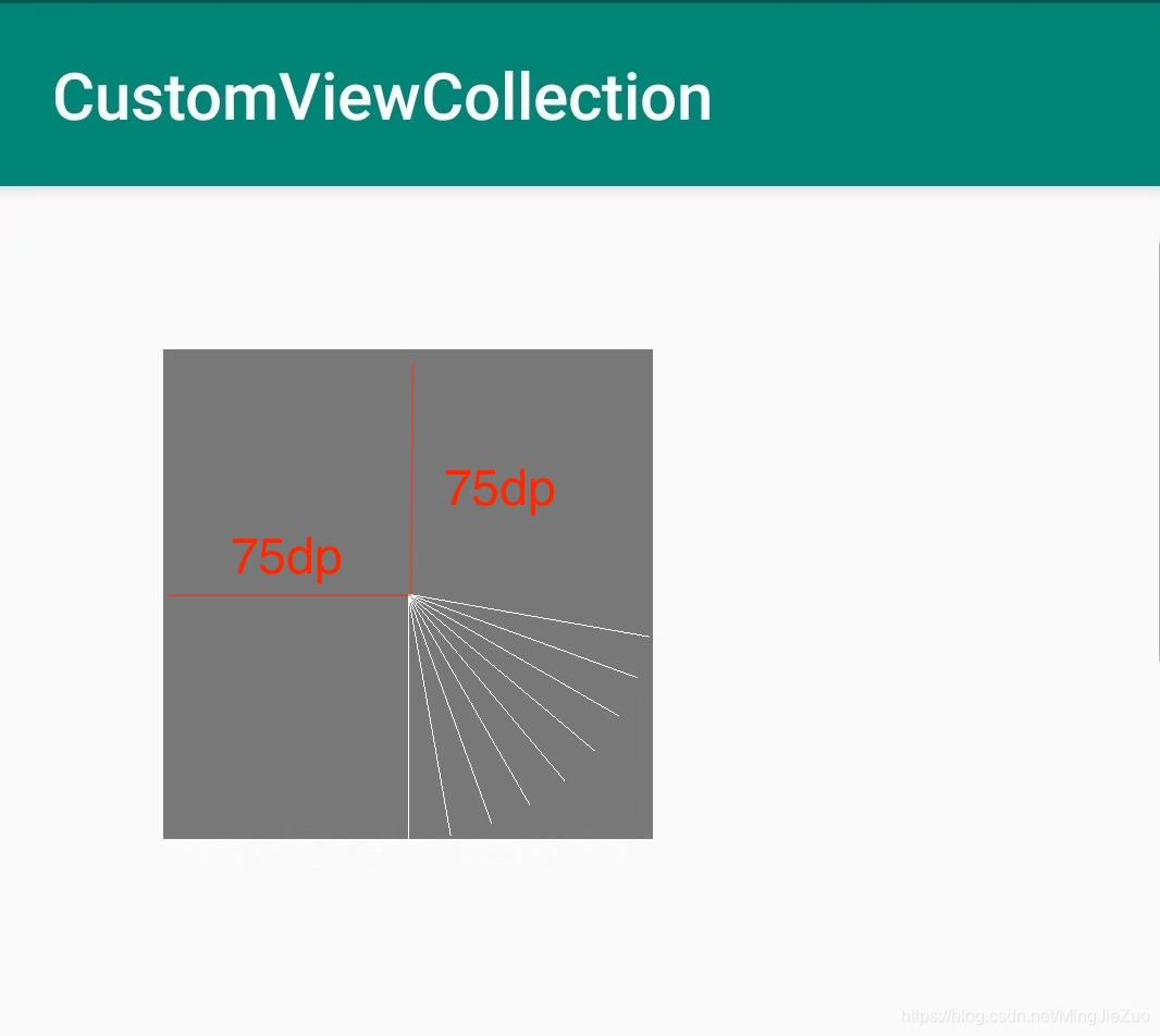
画布平移
在上面画布旋转代码的基础上,我们将画布中的线段起点挪动到view的中心点位置,代码片段如下:
    private void drawTranslate(Canvas canvas){
        /**
         * dx: 要在x中转换的距离
         * dy: 要在y中转换的距离
         */
        canvas.translate(CommentUtils.dip2px(mContext, 75)
                , CommentUtils.dip2px(mContext, 75));
    }
在onDraw中绘制线段,并平移旋转画布:
                // 锁定当前画布
                canvas.save();
                // 挪动画布
                drawTranslate(canvas);
                // 画线
                drawRotate(canvas);
                // 恢复画布
                canvas.restore();
在xml中的代码片段:
    <com.mjzuo.views.view.GeometricFigureView
        android:layout_width="150dp"
        android:layout_height="150dp"
        android:background="#787878"
        android:layout_marginLeft="50dp"
        android:layout_marginTop="50dp"
        custom:draw_type="12"
        />
效果图如下: