上一篇文章中,描述了在用户态下通过“ioctl”接口访问24系列i2c接口的EEPROM,本文描述调用EEPROM驱动接口实现访问。linux内核提供了完整的24系列EEPROM驱动,位于“kernel/drivers/misc”目录下(at24.c),可以直接使用。
编译系统:Ubuntu16.04
ARM硬件:firefly RK3399
ARM系统:firefly Ubuntu16.04(SDK)
连接i2c:i2c4
EEPROM:AT24C02
1. EEPROM驱动分析
24系列EEPROM是以i2c为接口的,不同厂家的芯片是可以相互兼容的,如atmel、st、microchip以及一些小众品牌。内核提供的源码是基于atmel的EEPROM(at24cxx)。
1.1 私有数据
struct at24_data {
	struct at24_platform_data chip;		/* 芯片信息 */
	struct memory_accessor macc;
	int use_smbus;						/* 如果使用smbus */
	int use_smbus_write;

	/*
	 * Lock protects against activities from other Linux tasks,
	 * but not from changes by other I2C masters.
	 */
	struct mutex lock;				/* 读写互斥锁 */
	struct bin_attribute bin;		/* 驱动匹配后生成sys目录信息 */

	u8 *writebuf;					/* 写缓冲区 */
	unsigned write_max;				/* 写限制最大空间 */
	unsigned num_addresses;

	/*
	 * Some chips tie up multiple I2C addresses; dummy devices reserve
	 * them for us, and we'll use them with SMBus calls.
	 */
	struct i2c_client *client[];/* i2c总线,这里是数组形式,表示会占用“多个”i2c总线,因为24系列EEPROM小于16Mbit时是八位寻址,超过256字节地址后采用i2c从地址进行“翻页”寻址*/
};
“at24_platform_data”在“kernel/include/linux/platform_data/at24.h”中声明。
struct at24_platform_data {
	u32		byte_len;		/* size (sum of all addr) */
	u16		page_size;		/* for writes */
	u8		flags;
#define AT24_FLAG_ADDR16	0x80	/* address pointer is 16 bit */
#define AT24_FLAG_READONLY	0x40	/* sysfs-entry will be read-only */
#define AT24_FLAG_IRUGO		0x20	/* sysfs-entry will be world-readable */
#define AT24_FLAG_TAKE8ADDR	0x10	/* take always 8 addresses (24c00) */

	void		(*setup)(struct memory_accessor *, void *context);
	void		*context;
};
1.2 常用型号匹配表
源码已经实现常用器件型号描述表,“struct i2c_device_id ”属性中,第一个是器件型号,第二个是器件i2c地址,描述表中器件的A0—A2地址选择脚默认是接地(0)。使用设备树描述时,“.compatible”属性必须与第一个属性一致(器件型号)。
static const struct i2c_device_id at24_ids[] = {
	/* needs 8 addresses as A0-A2 are ignored */
	{ "24c00", AT24_DEVICE_MAGIC(128 / 8, AT24_FLAG_TAKE8ADDR) },
	/* old variants can't be handled with this generic entry! */
	{ "24c01", AT24_DEVICE_MAGIC(1024 / 8, 0) },
	{ "24c02", AT24_DEVICE_MAGIC(2048 / 8, 0) },
	/* spd is a 24c02 in memory DIMMs */
	{ "spd", AT24_DEVICE_MAGIC(2048 / 8,
		AT24_FLAG_READONLY | AT24_FLAG_IRUGO) },
	{ "24c04", AT24_DEVICE_MAGIC(4096 / 8, 0) },
	/* 24rf08 quirk is handled at i2c-core */
	{ "24c08", AT24_DEVICE_MAGIC(8192 / 8, 0) },
	{ "24c16", AT24_DEVICE_MAGIC(16384 / 8, 0) },
	{ "24c32", AT24_DEVICE_MAGIC(32768 / 8, AT24_FLAG_ADDR16) },
	{ "24c64", AT24_DEVICE_MAGIC(65536 / 8, AT24_FLAG_ADDR16) },
	{ "24c128", AT24_DEVICE_MAGIC(131072 / 8, AT24_FLAG_ADDR16) },
	{ "24c256", AT24_DEVICE_MAGIC(262144 / 8, AT24_FLAG_ADDR16) },
	{ "24c512", AT24_DEVICE_MAGIC(524288 / 8, AT24_FLAG_ADDR16) },
	{ "24c1024", AT24_DEVICE_MAGIC(1048576 / 8, AT24_FLAG_ADDR16) },
	{ "at24", 0 },
	{ /* END OF LIST */ }
};
1.3 读函数
static ssize_t at24_eeprom_read(struct at24_data *at24, char *buf,
		unsigned offset, size_t count)
{
	struct i2c_msg msg[2];	/* i2c总线消息 */
	u8 msgbuf[2];
	struct i2c_client *client;
	unsigned long timeout, read_time;
	int status, i;

	memset(msg, 0, sizeof(msg));

	/*
	 * REVISIT some multi-address chips don't rollover page reads to
	 * the next slave address, so we may need to truncate the count.
	 * Those chips might need another quirk flag.
	 *
	 * If the real hardware used four adjacent 24c02 chips and that
	 * were misconfigured as one 24c08, that would be a similar effect:
	 * one "eeprom" file not four, but larger reads would fail when
	 * they crossed certain pages.
	 */

	/*
	 * Slave address and byte offset derive from the offset. Always
	 * set the byte address; on a multi-master board, another master
	 * may have changed the chip's "current" address pointer.
	 */
	client = at24_translate_offset(at24, &offset);/* 获取翻页偏移地址(总线)0x50/0x51/0x52等 */

	if (count > io_limit)
		count = io_limit;

	if (at24->use_smbus) {
		/* Smaller eeproms can work given some SMBus extension calls */
		if (count > I2C_SMBUS_BLOCK_MAX)
			count = I2C_SMBUS_BLOCK_MAX;
	} else {
		/*
		 * When we have a better choice than SMBus calls, use a
		 * combined I2C message. Write address; then read up to
		 * io_limit data bytes. Note that read page rollover helps us
		 * here (unlike writes). msgbuf is u8 and will cast to our
		 * needs.
		 */
		i = 0;
		if (at24->chip.flags & AT24_FLAG_ADDR16)	/* 16bit寻址时处理,先传输高8bit地址  */
			msgbuf[i++] = offset >> 8;
		msgbuf[i++] = offset;

		msg[0].addr = client->addr;
		msg[0].buf = msgbuf;
		msg[0].len = i;

		msg[1].addr = client->addr;	/* i2c从地址 */
		msg[1].flags = I2C_M_RD;	/* 读标识 */
		msg[1].buf = buf;
		msg[1].len = count;
	}

	/*
	 * Reads fail if the previous write didn't complete yet. We may
	 * loop a few times until this one succeeds, waiting at least
	 * long enough for one entire page write to work.
	 */
	timeout = jiffies + msecs_to_jiffies(write_timeout);
	do {
		read_time = jiffies;
		if (at24->use_smbus) {	/* 使用smbus总线 */
			status = i2c_smbus_read_i2c_block_data_or_emulated(client, offset,
									   count, buf);
		} else {
			status = i2c_transfer(client->adapter, msg, 2);	/* 使用i2c总线(默认)*/
			if (status == 2)
				status = count;
		}
		dev_dbg(&client->dev, "read %zu@%d --> %d (%ld)\n",
				count, offset, status, jiffies);

		if (status == count)
			return count;

		/* REVISIT: at HZ=100, this is sloooow */
		msleep(1);
	} while (time_before(read_time, timeout));	/* 读超时处理 */

	return -ETIMEDOUT;
}
1.4 写函数
static ssize_t at24_eeprom_write(struct at24_data *at24, const char *buf,
		unsigned offset, size_t count)
{
	struct i2c_client *client;
	struct i2c_msg msg;		/* i2c总线消息 */
	ssize_t status = 0;
	unsigned long timeout, write_time;
	unsigned next_page;

	if (offset + count > at24->chip.byte_len)
		return -EINVAL;

	/* Get corresponding I2C address and adjust offset */
	client = at24_translate_offset(at24, &offset);	/* 获取翻页偏移地址(总线)0x50/0x51/0x52等 */

	/* write_max is at most a page */
	if (count > at24->write_max)	/* 限制范围 */
		count = at24->write_max;

	/* Never roll over backwards, to the start of this page */
	next_page = roundup(offset + 1, at24->chip.page_size);/* 取整数下一块地址 */
	if (offset + count > next_page)						  /* 计算非对块地址 */
		count = next_page - offset;

	/* If we'll use I2C calls for I/O, set up the message */
	if (!at24->use_smbus) {
		int i = 0;

		msg.addr = client->addr;
		msg.flags = 0;		/* 写标识 */

		/* msg.buf is u8 and casts will mask the values */
		msg.buf = at24->writebuf;
		if (at24->chip.flags & AT24_FLAG_ADDR16)	/* 16bit 寻址处理,先传输高8bit地址 */
			msg.buf[i++] = offset >> 8;

		msg.buf[i++] = offset;
		memcpy(&msg.buf[i], buf, count);
		msg.len = i + count;
	}

	/*
	 * Writes fail if the previous one didn't complete yet. We may
	 * loop a few times until this one succeeds, waiting at least
	 * long enough for one entire page write to work.
	 */
	timeout = jiffies + msecs_to_jiffies(write_timeout);
	do {
		write_time = jiffies;
		if (at24->use_smbus_write) {	/* 使用sembus总线 */
			switch (at24->use_smbus_write) {
			case I2C_SMBUS_I2C_BLOCK_DATA:
				status = i2c_smbus_write_i2c_block_data(client,
						offset, count, buf);
				break;
			case I2C_SMBUS_BYTE_DATA:
				status = i2c_smbus_write_byte_data(client,
						offset, buf[0]);
				break;
			}

			if (status == 0)
				status = count;
		} else {	/* 使用i2c总线(默认)*/
			status = i2c_transfer(client->adapter, &msg, 1);
			if (status == 1)
				status = count;
		}
		dev_dbg(&client->dev, "write %zu@%d --> %zd (%ld)\n",
				count, offset, status, jiffies);

		if (status == count)
			return count;

		/* REVISIT: at HZ=100, this is sloooow */
		msleep(1);
	} while (time_before(write_time, timeout));/* 写超时处理 */

	return -ETIMEDOUT;
}
1.5 匹配函数
static int at24_probe(struct i2c_client *client, const struct i2c_device_id *id)
{
	struct at24_platform_data chip;
	kernel_ulong_t magic = 0;
	bool writable;
	int use_smbus = 0;
	int use_smbus_write = 0;
	struct at24_data *at24;
	int err;
	unsigned i, num_addresses;

	if (client->dev.platform_data) {	/* 如果存在,优先使用platform(设备树)描述信息 */
		chip = *(struct at24_platform_data *)client->dev.platform_data;
	} else {
		if (id) {
			magic = id->driver_data;	/* 使用at24_ids描述表 */
		} else {
			const struct acpi_device_id *aid;

			aid = acpi_match_device(at24_acpi_ids, &client->dev);	/* acpi表在嵌入式中比较少用 */
			if (aid)
				magic = aid->driver_data;
		}
		if (!magic)
			return -ENODEV;

		chip.byte_len = BIT(magic & AT24_BITMASK(AT24_SIZE_BYTELEN));
		magic >>= AT24_SIZE_BYTELEN;
		chip.flags = magic & AT24_BITMASK(AT24_SIZE_FLAGS);
		/*
		 * This is slow, but we can't know all eeproms, so we better
		 * play safe. Specifying custom eeprom-types via platform_data
		 * is recommended anyhow.
		 */
		chip.page_size = 1;

		/* update chipdata if OF is present */
		at24_get_ofdata(client, &chip);

		chip.setup = NULL;
		chip.context = NULL;
	}

	if (!is_power_of_2(chip.byte_len))
		dev_warn(&client->dev,
			"byte_len looks suspicious (no power of 2)!\n");
	if (!chip.page_size) {
		dev_err(&client->dev, "page_size must not be 0!\n");
		return -EINVAL;
	}
	if (!is_power_of_2(chip.page_size))
		dev_warn(&client->dev,
			"page_size looks suspicious (no power of 2)!\n");

	.........

	if (chip.flags & AT24_FLAG_TAKE8ADDR)		/* 寻址类型选择 */
		num_addresses = 8;
	else
		num_addresses =	DIV_ROUND_UP(chip.byte_len,
			(chip.flags & AT24_FLAG_ADDR16) ? 65536 : 256);

	at24 = devm_kzalloc(&client->dev, sizeof(struct at24_data) +
		num_addresses * sizeof(struct i2c_client *), GFP_KERNEL);
	if (!at24)
		return -ENOMEM;

	mutex_init(&at24->lock);
	at24->use_smbus = use_smbus;
	at24->use_smbus_write = use_smbus_write;
	at24->chip = chip;
	at24->num_addresses = num_addresses;

	/*
	 * Export the EEPROM bytes through sysfs, since that's convenient.
	 * By default, only root should see the data (maybe passwords etc)
	 */
	sysfs_bin_attr_init(&at24->bin);		/* 初始化生成文件目录信息 */
	at24->bin.attr.name = "eeprom";			/* 文件名称,匹配成功,在“/sys/bus/i2c/device/4-0050”目录下生成 */
	at24->bin.attr.mode = chip.flags & AT24_FLAG_IRUGO ? S_IRUGO : S_IRUSR;
	at24->bin.read = at24_bin_read;
	at24->bin.size = chip.byte_len;

	at24->macc.read = at24_macc_read;

	writable = !(chip.flags & AT24_FLAG_READONLY);
	if (writable) {
		if (!use_smbus || use_smbus_write) {

			unsigned write_max = chip.page_size;

			at24->macc.write = at24_macc_write;

			at24->bin.write = at24_bin_write;
			at24->bin.attr.mode |= S_IWUSR;

			if (write_max > io_limit)
				write_max = io_limit;
			if (use_smbus && write_max > I2C_SMBUS_BLOCK_MAX)
				write_max = I2C_SMBUS_BLOCK_MAX;
			at24->write_max = write_max;

			/* buffer (data + address at the beginning) */
			at24->writebuf = devm_kzalloc(&client->dev,
				write_max + 2, GFP_KERNEL);
			if (!at24->writebuf)
				return -ENOMEM;
		} else {
			dev_warn(&client->dev,
				"cannot write due to controller restrictions.");
		}
	}

	at24->client[0] = client;		/* 至少使用一根i2c总线 */

	/* use dummy devices for multiple-address chips */
	for (i = 1; i < num_addresses; i++) {		/* 超过256地址后,分配一个i2c总线(地址)作“翻页”功能 */
		at24->client[i] = i2c_new_dummy(client->adapter,
					client->addr + i);
		if (!at24->client[i]) {
			dev_err(&client->dev, "address 0x%02x unavailable\n",
					client->addr + i);
			err = -EADDRINUSE;
			goto err_clients;
		}
	}

	err = sysfs_create_bin_file(&client->dev.kobj, &at24->bin);	/* 创建sys文件,支持echo/cat等脚本访问 */
	if (err)
		goto err_clients;

	i2c_set_clientdata(client, at24);

	dev_info(&client->dev, "%zu byte %s EEPROM, %s, %u bytes/write\n",
		at24->bin.size, client->name,
		writable ? "writable" : "read-only", at24->write_max);
	if (use_smbus == I2C_SMBUS_WORD_DATA ||
	    use_smbus == I2C_SMBUS_BYTE_DATA) {
		dev_notice(&client->dev, "Falling back to %s reads, "
			   "performance will suffer\n", use_smbus ==
			   I2C_SMBUS_WORD_DATA ? "word" : "byte");
	}

	/* export data to kernel code */
	if (chip.setup)
		chip.setup(&at24->macc, chip.context);

	return 0;

err_clients:
	for (i = 1; i < num_addresses; i++)
		if (at24->client[i])
			i2c_unregister_device(at24->client[i]);

	return err;
}
2. 使用驱动
2.1 添加设备树
AT24C02连接在i2c4上,在“kernel/arch/arm64/boot/dts/rockchip/rk3399-firefly-core.dtsi”中的i2c4节点加入EEPROM节点。
 eeprom: eeprom@50{
                compatible = "atmel,24c02";	/* 型号名称与驱动描述表一致,厂商名称可省 */
                reg = <0x50>;			/* 器件地址 */
                pagesize = <8>;			/* 连续写页大小,24c02为8字节 */
                status = "okay";
        };
2.2 内核配置
方式【1】
进入kernel目录执行“make menuconfig”,选择如下条目,将EERPOM编译到内核(“*”),“M”表示编译成单独模块(.ko)。
Device Drivers  --->
    Misc devices  --->
        EEPROM support  --->
            <*> I2C EEPROMs / RAMs / ROMs from most vendors
方式【2】
调用firefly的编译脚本编译内核时,会首先将“firefly_linux_defconfig”默认配置写入内核配置文件“.config”中,会覆盖方式【1】中的部分配置,但如果去掉脚本中的内核配置后导致编译失败(为什么每次编译都需写入默认配置?)。
因此,在firefly的默认内核配置文件“kernel/arc/arm64/configs/firefly_linux_defconfig”加入EEPROM驱动编译使能脚本。暂时推荐使用第二种方式。
CONFIG_EEPROM_AT24=y
2.3 编译内核
在sdk目录下执行“./build.sh kernel”编译内核。编译成功在“kernel”目录下生成内核和设备树打包文件“boot.img”,烧录替换板子内核和设备树。
3. 测试
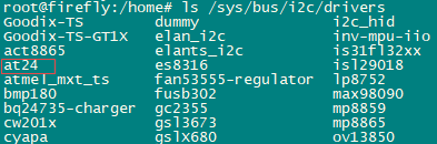
【1】查看驱动,加载成功,在“/sys/bus/i2c/drivers”目录生成i2c驱动名称
【2】查看驱动的sys文件,位于“/sys/busi2c/device/4-0050”中

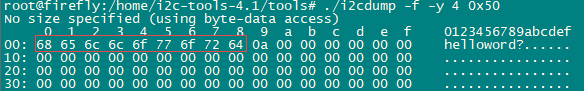
【3】访问EEPROM
sys文件支持“echo”、“cat”访问。

也可以借助“i2ctools”工具验证。