vivado设计4bit先行进位加法器 并使用 4bit CLA 组合设计一个 16bit 加法器
前言
此次实验使用软件为Vivado,相关实验说明文档参考链接:
github:https://github.com/Junzhou-Chen/input-adder
CSDN:https://download.csdn.net/download/weixin_51717597/85559470
因为考虑到大多是第一次使用,所以整体写的较为繁琐,有基础可自行跳转至相关位置查看代码即可
配置环境和文件
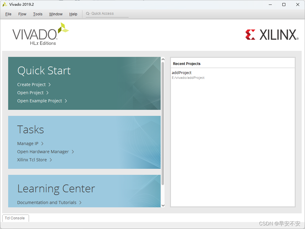
1、打开vivado
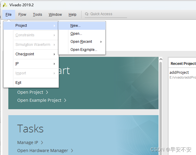
选择“File”->“New Project”
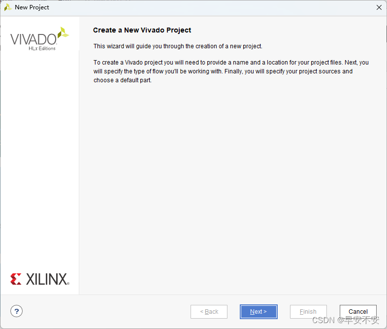
选择next
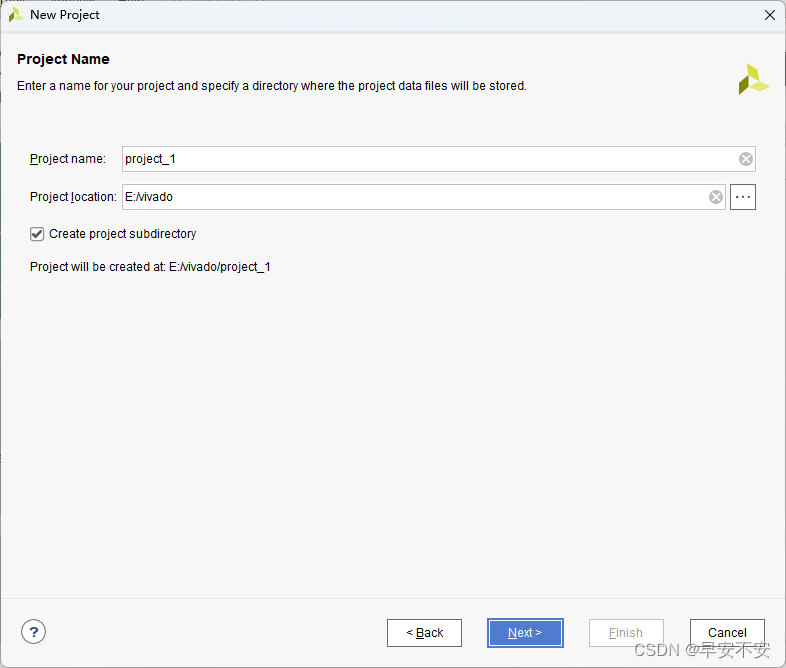
输入工程名称和文件路径
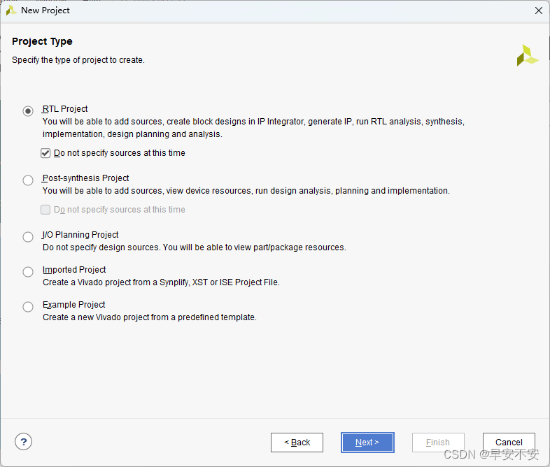
在工程类型“Project Type”选择界面,选择“RTL Project”,勾选“Do not specify sources at this time”
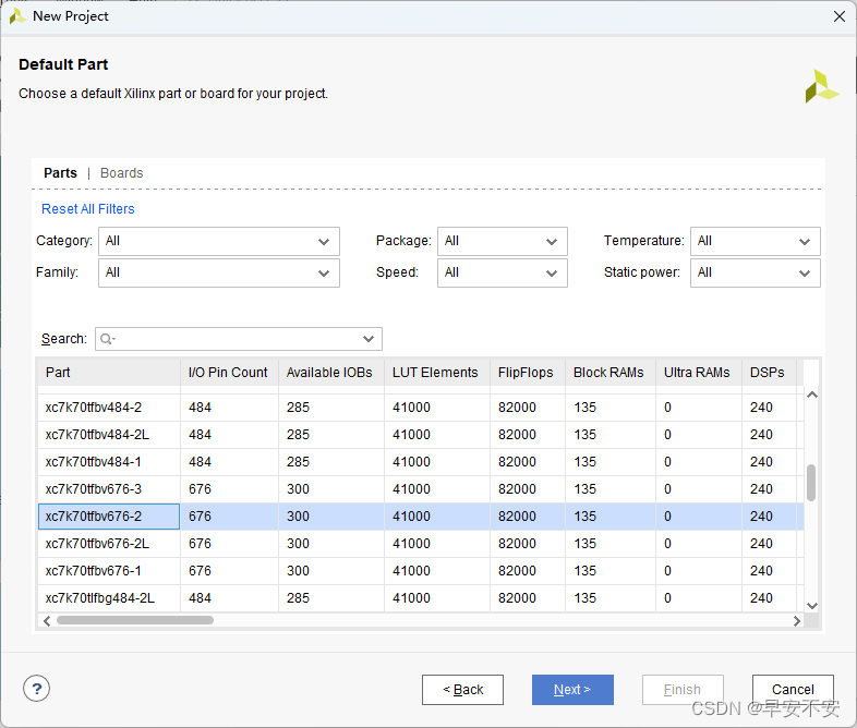
在“Default Part”FPGA 器件选择界面,指定所用的 FPGA 器件或开发板。“Parts”指 FPGA 芯片,包含了 Vivado2019.2 所支持的芯片型号;“Boards ”指的是Vivado2019.2 所支持的开发板。这里选“Parts”,然后在筛选器的“Family”中选择“Artix- 7”,在“Package”中选择“fbg676”,在筛选得到的型号里面选择“xc7a200tfbg676-2”,点击“Next”,根据向导,单击“Finish”按钮即完成整个工程的创建
选择finish
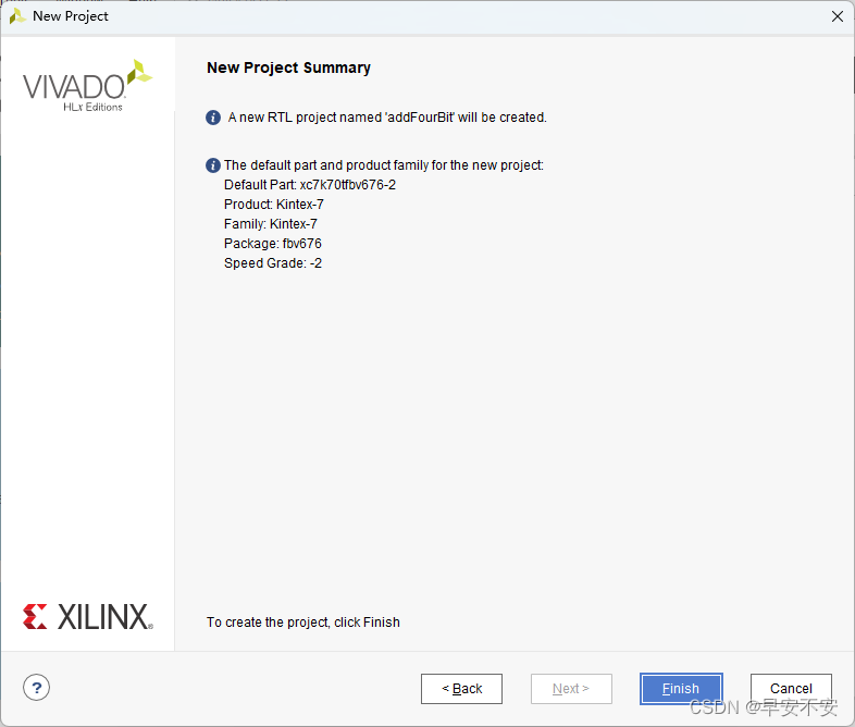
创建完成!
添加文件
添加已有 Verilog 文件的方法如下:在“PROJECT MANAGER”下点击“Add Sources”,选择“Add or create design sources”。
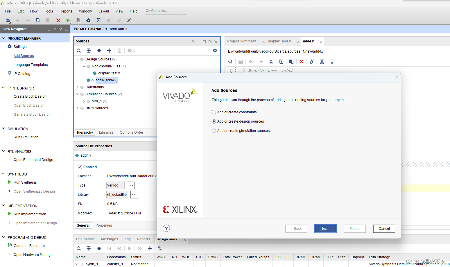
可以添加已有文件,也可以自己创建文件
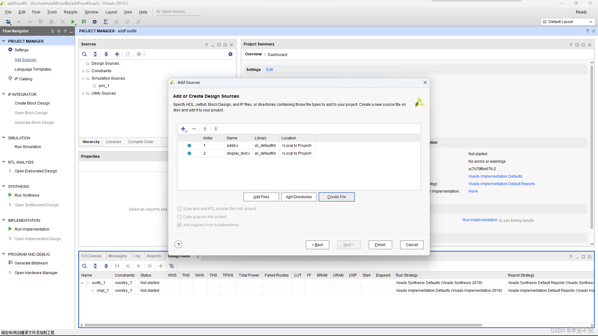
之后选择finish即可
实验代码测试
添加文件add.v和display.v文件,代码分别如下
add.v:
`timescale 1ns / 1ps
//*************************************************************************
// > 文件名:adder.v
// > 描述:加法器
// > 作者:早安不安
// > time:2022-06-04
//*************************************************************************
module adder(
 input [31:0] operand1,
 input [31:0] operand2,
 input cin,
 output [31:0] result,
 output cout
 );
 assign {

    cout,result} = operand1 + operand2 + cin;
endmodule
display.v
`timescale 1ns / 1ps //仿真单位时间为 1ns,精度为 1ps
module testbench;
 // Inputs
 reg [31:0] operand1;
 reg [31:0] operand2;
 reg cin;
 // Outputs
 wire [31:0] result;
 wire cout;
 // Instantiate the Unit Under Test (UUT)
 adder uut (
 .operand1(operand1),
 .operand2(operand2),
 .cin(cin),
 .result(result),
 .cout(cout)
 );
 initial begin
 // Initialize Inputs
 operand1 = 0;
 operand2 = 0;
 cin = 0;
 // Wait 100 ns for global reset to finish
 #100;
 // Add stimulus here
 end
 always #10 operand1 = $random; //$random 为系统任务,产生一个随机的 32 位数
 always #10 operand2 = $random; //#10 表示等待10 个单位时间(10ns),即每过10ns,赋值一个随机的 32 位数
 always #10 cin = {

    $random} % 2; //加了拼接符,{$random}产生一个非负数,除 2 取余得到 0 或 1;进位
endmodule
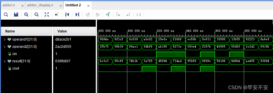
运行测试
在左侧的导航栏中点击“Run Simulation”,选择“Run Behavioral Simulation”可进行仿真验证。
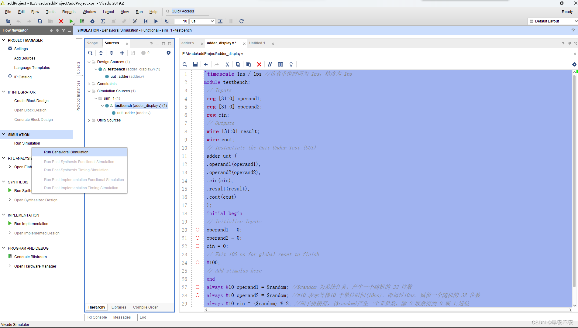
如果没有语法错误,弹出界面如图所示
4bit先行进位加法器
原理
参考博客:https://www.jianshu.com/p/6ce9cad8b467
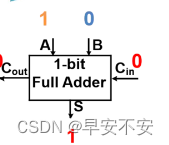
串行加法器:
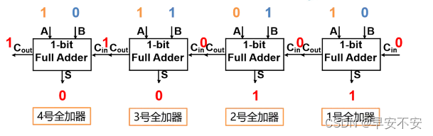
并行进位加法器
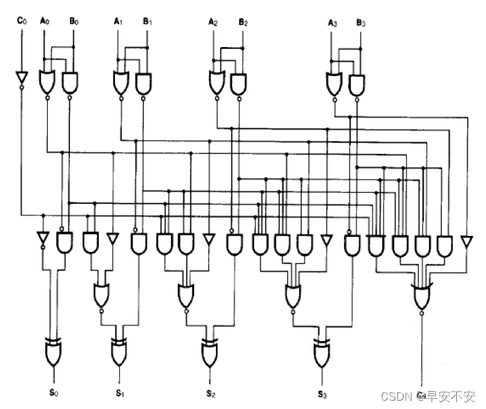
进位算法
本位数值
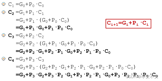
公式整理如下:
生成(Generate)信号: G n = A n ⋅ B n G_n=A_n \cdot B_n Gn=An⋅Bn
传播(Propagate)信号: P n = A n + B n P_n=A_n+B_n Pn=An+Bn
C n + 1 = G n + P n ⋅ C n C_{n+1} = G_n+P_n\cdot C_n Cn+1=Gn+Pn⋅Cn
S n = A n ⨁ B n ⨁ C n S_n = A_n\bigoplus B_n \bigoplus C_{n} Sn=An⨁Bn⨁Cn
代码实现
其中注释很详细,大家参考注释来即可
其中add4.v文件是4bit超前进位加法器实现代码,display_test.v代码是测试代码
add4.v
`timescale 1ns / 1ps
//
// Company: HoHai University
// Engineer: 早安不安
// Create Date: 2022/06/05
// Design Name: 4bit先行进位加法器方法
// Module Name: add4
// Project Name: 4bit先行进位加法器
// Description: 超前进位加法器优化改进行波进位器的关键路径,通过采用并行计算进位的
//              方法,解决了行波进位加法器的进位依赖问题。
// Revision 0.01 - File Created
//

module add4(
    // 定义成员变量
    input[3:0] A,   // 输入A
    input[3:0] B,   // 输入B
    input C_in,     // 进位输入
    output[3:0]S,   // S输出
    output C_out    // 进位输出
    );
    wire[3:0] G ,P ,C ;
    assign G = A & B; // 生成信号(Generate)
    assign P = A ^ B; // 传播信号(Propagate)
    // 进位信号
    assign C[0] = C_in;
    assign C[1] = G[0] | (P[0] & C[0]);
    assign C[2] = G[1] | (P[1] & (G[0] | (P[0] & C[0])));
    assign C[3] = G[2] | (P[2] & (G[1] | (P[1] & (G[0] | (P[0] & C[0])))));
    assign C_out = G[3] | (P[3] & (G[2] | (P[2] & (G[1] | (P[1] & (G[0] | (P[0] & C[0])))))));
    assign S = A ^ B ^ C;
endmodule
display_test.v
`timescale 1ns / 1ps //仿真单位时间为 1ns,精度为 1ps
module display_test;
 // Inputs
 reg [3:0] A;
 reg [3:0] B;
 reg cin;
 // Outputs
 wire [3:0] S;
 wire cout;
 // Instantiate the Unit Under Test (UUT)
 add4 test (
 .A(A),
 .B(B),
 .C_in(cin),
 .S(S),
 .C_out(cout)
 );
 initial begin
 // Initialize Inputs
 A = 0;
 B = 0;
 cin = 0;
 // Wait 100 ns for global reset to finish
 #100;
 // Add stimulus here
 end
 always #10 A = $random; //$random 为系统任务,产生一个随机的 32 位数
 always #10 B = $random; //#10 表示等待10 个单位时间(10ns),即每过10ns,赋值一个随机的 32 位数
 always #10 cin = {

    $random} % 2; //加了拼接符,{$random}产生一个非负数,除 2 取余得到 0 或 1
endmodule
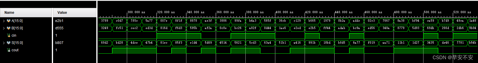
运行结果
4bit CLA 组合设计 16bit 加法器
其实基本原理和之前的4bit超前进位加法器相似,但这里方便起见,使用串行加法器方式,即将16位划分为4个4位,从最低4位,不断向上运算
文件结果上,16位加法器依赖之前的4位超前进位加法器,所以需要引用该文件,文件结构如下:
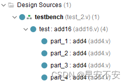
代码
其中add16.v文件是4bit CLA 组合设计 16bit 加法器代码,test2.v代码是测试代码,同时依赖之前设计好的4
bit超前进位加法器
add16.v
`timescale 1ns / 1ps
//
// Company: HoHai University
// Engineer: 早安不安
// Create Date: 2022/06/05
// Design Name: 4bit CLA 组合设计 16bit 加法器方法
// Module Name: add16
// Project Name: 4bit CLA 组合设计 16bit 加法器
// Description: 使用之前设计好的4bit超前进位加法器实现16 bit加法器
//              实现原理,通过串行加法器实现,相对简单
// Revision 0.01 - File Created
//

module add16(
    input[15:0] A,
    input[15:0] B,
    input C_in,
    output[15:0] S,
    output C_out
    );
    wire[0:2] C;
    add4 part_1(.A(A[3:0]), .B(B[3:0]), .C_in(C_in),.S(S[3:0]),.C_out(C[0]));
    add4 part_2(.A(A[7:4]), .B(B[7:4]),.C_in(C[0]),.S(S[7:4]),.C_out(C[1]));
    add4 part_3(.A(A[11:8]), .B(B[11:8]),.C_in(C[1]),.S(S[11:8]),.C_out(C[2]));
    add4 part_4(.A(A[15:12]), .B(B[15:12]),.C_in(C[2]),.S(S[15:12]),.C_out(C_out));
endmodule
test2.v
`timescale 1ns / 1ps //仿真单位时间为 1ns,精度为 1ps
module test2;
 // Inputs
 reg [15:0] A;
 reg [15:0] B;
 reg cin;
 // Outputs
 wire [15:0] S;
 wire cout;
 // Instantiate the Unit Under Test (UUT)
 add16 test (
 .A(A),
 .B(B),
 .C_in(cin),
 .S(S),
 .C_out(cout)
 );
 initial begin
 // Initialize Inputs
 A = 0;
 B = 0;
 cin = 0;
 // Wait 100 ns for global reset to finish
 #100;
 // Add stimulus here
 end
 always #10 A = $random; //$random 为系统任务,产生一个随机的 32 位数
 always #10 B = $random; //#10 表示等待10 个单位时间(10ns),即每过10ns,赋值一个随机的 32 位数
 always #10 cin = {

    $random} % 2; //加了拼接符,{$random}产生一个非负数,除 2 取余得到 0 或 1
endmodule
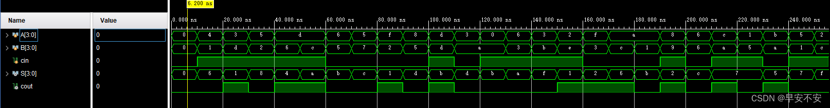
运行结果