0.前言
有关鱼眼相机成像模型相关知识,参考我的这篇文章。通过对鱼眼相机做内参标定,可以得到相机的内参和畸变参数
。利用上述参数,可以对鱼眼相机获取的原始畸变图像做畸变校正。
1.畸变校正原理

简单回顾下鱼眼相机成像模型,上图中相机坐标系的X轴垂直屏幕向外;且成像平面位于投影中心前方以便于分析。对于相机坐标系中的一点,根据鱼眼成像模型其投影至点
;如果使用小孔成像模型,则会投影至点
,这里可直观地看出前者相比于后者可以获取更加宽广的视野。同时根据这张图可以得到小孔成像模型的映射点
到鱼眼相机成像模型映射点
的映射关系,这就是鱼眼相机图像畸变校正的基础原理。由于映射关系为
,得到的图像视野范围一般会小于原图。
鱼眼相机图像畸变校正具体流程如下:
1)对于目标图像中每个像素点,利用内参信息计算得到对应的归一化成像平面映射点
2)利用鱼眼相机内参和畸变参数计算点对应的映射点
3)一般求得的为小数,使用插值算法得到其像素值
注意:步骤1)和2)中的内参,可以相同也可以不同,因为并未要求目标图像的成像模型参数和原始鱼眼相机相同。
2.畸变校正代码实现
首先自己手写实现
void MyFisheyeImageUndistortion()
{
	cv::Mat img, undistortImg;
	cv::Matx33d K, P;
	cv::Vec4d D;
	cv::Mat mapX, mapY;
	img = cv::imread("img.bmp");
	undistortImg.create(img.size(), img.type());

	K(0, 0) = 348.52; K(0, 1) = 0; K(0, 2) = 640.19;
	K(1, 0) = 0; K(1, 1) = 348.52; K(1, 2) = 358.56;
	K(2, 0) = 0; K(2, 1) = 0; K(2, 2) = 1;

	D(0) = 0.066258;
	D(1) = 0.039769;
	D(2) = -0.026906;
	D(3) = 0.003342;

	P = K;
	P(0, 0) /= 1.5;
	P(1, 1) /= 1.5;// 一般另P=K,这里减小了小孔成像模型中的f,得到的畸变校正后的图像视野会扩大

	float x, y, theta, theta_d, r, x_origin, y_origin;
	for (int v = 0; v < undistortImg.rows; v++)
	{
		for (int u = 0; u < undistortImg.cols; u++)
		{
			float r, g, b;
			x = (u - P(0, 2)) / P(0, 0);
			y = (v - P(1, 2)) / P(1, 1);
			theta = atan(sqrt(x*x + y*y));
			float theta_2 = theta * theta;
			theta_d = theta*(1 + D(0)*theta_2 + D(1)*theta_2 * theta_2
				+ D(2)*theta_2*theta_2*theta_2 +
				D(3)*theta_2*theta_2*theta_2*theta_2);
			x_origin = K(0, 0)*theta_d*x / (sqrt(x*x + y*y)) + K(0, 2);
			y_origin = K(1, 1)*theta_d*y / (sqrt(x*x + y*y)) + K(1, 2);
			if (x_origin < 0 || x_origin > img.cols - 1
				|| y_origin < 0 || y_origin > img.rows - 1)
			{
				undistortImg.at<cv::Vec3b>(v, u) = cv::Vec3b(0, 0, 0);
			}
			else// 只是为了验证畸变校正流程,为方便这里用了最近邻差值
			{
				undistortImg.at<cv::Vec3b>(v, u) = img.at<cv::Vec3b>((int)y_origin, (int)x_origin);
			}
		}
	}
	cv::imshow("src", img);
	cv::imshow("corrected", undistortImg);
	cv::imwrite("my_corrected.bmp", undistortImg);
	cv::waitKey();

}


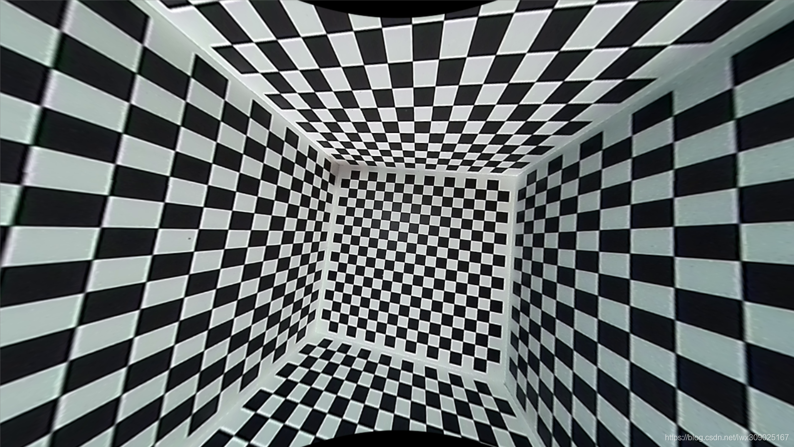
运行效果如上图所示,左方为原始图像,右方为畸变校正后的图像;由于手动减小了小孔成像模型中的f,结果图像在竖直方向的视野会部分超出原图,导致产生黑色填充区域。
之后调用OpenCV接口实现畸变校正,代码如下。
void OpenCVFisheyeImageUndistortion()
{
	cv::Mat img, undistortImg;
	cv::Matx33d K, P;
	cv::Vec4d D;
	cv::Mat mapX, mapY;
	img = cv::imread("img.bmp");

	K(0, 0) = 348.52; K(0, 1) = 0; K(0, 2) = 640.19;
	K(1, 0) = 0; K(1, 1) = 348.52; K(1, 2) = 358.56;
	K(2, 0) = 0; K(2, 1) = 0; K(2, 2) = 1;

	D(0) = 0.066258;
	D(1) = 0.039769;
	D(2) = -0.026906;
	D(3) = 0.003342;

	P = K;
	P(0, 0) /= 1.5;
	P(1, 1) /= 1.5;

	cv::fisheye::initUndistortRectifyMap(K, D, cv::Matx33d::eye(),
		P, cv::Size(img.cols, img.rows), CV_16SC2, mapX, mapY);

	cv::remap(img, undistortImg, mapX, mapY, CV_INTER_LINEAR);
	cv::imshow("src", img);
	cv::imshow("corrected", undistortImg);
	cv::imwrite("corrected3.bmp", undistortImg);
	cv::waitKey();
}
运行结果如下图所示。

3.原始图像向畸变校正后图像映射
上面给出了畸变校正后图像向原始图像的映射计算,不过有时候我们需要反向计算原始图像中某点对应的畸变校正后的像素坐标。譬如在原始图像中计算得到一个特征点,之后需要在畸变校正后的图像中进一步计算其精确位置,就需要先得到特征点在畸变校正后图像的坐标点。由原图中点映射至畸变校正后图像中的
,推导过程如下。
首先为了简化推导过程,假设鱼眼相机内参中,之后
其中存在一个从计算得到
的过程;另
,问题转换为计算
的解。可以使用二分法进行解的近似求解。
这里给出实现代码,在原图(601,249)位置手动添加一个红圈,计算其在畸变校正后图像中的坐标,得到的位置为(613,284);在畸变校正后的图像中确认该结果正确。
void ProjectPointFromOriginToUndistorted(cv::Point2f input, cv::Point2f& output)
{
	cv::Matx33d K, P;
	cv::Vec4d D;
	float x, y, theta, theta_d, r, x_origin, y_origin;
	float theta_cal[2], d_theta;

	K(0, 0) = 348.52; K(0, 1) = 0; K(0, 2) = 640.19;
	K(1, 0) = 0; K(1, 1) = 348.52; K(1, 2) = 358.56;
	K(2, 0) = 0; K(2, 1) = 0; K(2, 2) = 1;

	D(0) = 0.066258;
	D(1) = 0.039769;
	D(2) = -0.026906;
	D(3) = 0.003342;

	P = K;
	P(0, 0) /= 1.5;
	P(1, 1) /= 1.5;// 一般另P=K,这里减小了小孔成像模型中的f,得到的畸变校正后的图像视野会扩大

	x_origin = input.x - K(0, 2);
	y_origin = input.y - K(1, 2);
	theta_d = sqrt(x_origin*x_origin + y_origin*y_origin)
		/ K(0, 0);
	theta_cal[0] = 0;
	theta_cal[1] = CV_PI / 2;
	d_theta = fabs(theta_cal[1] - theta_cal[0]);
	while (d_theta > 0.01)
	{
		float val[3];
		float middle_theta_cal = 0.5 * (theta_cal[1] + theta_cal[0]);

		val[0] = theta_cal[0] + D(0)*pow(theta_cal[0], 3)
			+ D(1)*pow(theta_cal[0], 5) + D(2)*pow(theta_cal[0], 7)
			+ D(3)*pow(theta_cal[0], 9) - theta_d;

		val[1] = theta_cal[1] + D(0)*pow(theta_cal[1], 3)
			+ D(1)*pow(theta_cal[1], 5) + D(2)*pow(theta_cal[1], 7)
			+ D(3)*pow(theta_cal[1], 9) - theta_d;

		val[2] = middle_theta_cal + D(0)*pow(middle_theta_cal, 3)
			+ D(1)*pow(middle_theta_cal, 5) + D(2)*pow(middle_theta_cal, 7)
			+ D(3)*pow(middle_theta_cal, 9) - theta_d;

		if (fabs(val[2]) < 1e-6)
		{
			break;
		}
		if (val[0] * val[2] > 0)
		{
			theta_cal[0] = middle_theta_cal;
		}
		else
		{
			theta_cal[1] = middle_theta_cal;
		}
		d_theta = theta_cal[1] - theta_cal[0];
	}

	theta = 0.5 * (theta_cal[1] + theta_cal[0]);
	x = tan(theta) / sqrt(x_origin*x_origin + y_origin*y_origin) * x_origin;
	y = tan(theta) / sqrt(x_origin*x_origin + y_origin*y_origin) * y_origin;
	output.x = x*P(0, 0) + P(0, 2);
	output.y = y*P(1, 1) + P(1, 2);
}