本节内容将基于机器视觉带着大家进行应用实训。机器视觉是人工智能正在快速发展的一个分支,简单说来机器视觉就是用机器代替人眼来做测量和判断。机器视觉系统是通过机器视觉产品(即图像摄取装置,分CMOS和CCD两种)将被摄取目标转换成图像信号,传送给专用的图像处理系统,得到被摄目标的形态信息,根据像素分布和亮度、颜色等信息,转变成数字化信号;图像系统对这些信号进行各种运算来抽取目标的特征,进而根据判别的结果来控制现场的设备动作。
机器视觉基础主要包含二维码识别、颜色识别等。
机器视觉系统最基本的特点就是提高生产的灵活性和自动化程度,在一些不适于人工作业的危险工作环境或者人工视觉难以满足要求的场合,常用机器视觉来替代人工视觉。同时在大批量重复性工业生产过程中,用机器视觉检测方法可以大大提高生产的效率和自动化程度。下面我们将结合机器视觉基础,基于开源的机器人平台,进行桌面机械臂搬运、颜色追踪等应用开发。
1. 视觉二维码识别
二维码的应用渗透到生活的方方面面,如手机购物、微信登录等,二维码常见的分类有矩阵式、堆叠式/行排式。具有代表性的矩阵式二维条码有Code One、Maxi Code、QR Code、 Data Matrix等;具有代表性的行排式二维条码有Code 16K、Code 49、PDF417等。
二维码的使用分为:生成二维码、识别已生成的二维码。这里我们主要是识别已生成的二维码(矩阵式二维码)。
设计思路
本实验主要是基于矩阵式二维码进行识别。QR码(Quick Response Code)是在正方形二维矩阵内通过黑白标识编码二进制位从而编码数据。
实现思路
利用摄像头采集二维码信息,利用zbar库识别后把结果显示在屏幕上。
器材准备
生成QR Code码(可以用在线编辑器生成)、摄像头。
下面是为本实验准备的二维码:(当然大家也可以直接打开微信二维码进行识别)

操作步骤
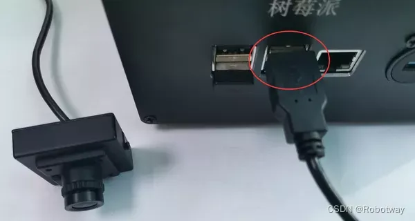
第一步:连接电路。将摄像头与控制盒进行连接。

第二步:下载文末资料中的参考程序color_experiment_ws\src\qr_detection\scripts\QrCode_Detection.py:
#!/usr/bin/env python

#!coding=utf-8

#write by leo at 2018.04.26

#function:

#1, Get live_video from the webcam.

#2, With ROS publish Image_info (to yolo and so on).

#3, Convert directly, don't need to save pic at local.

# import the necessary packages

import simple_barcode_detection

import zbar

from PIL import Image

import rospy

from sensor_msgs.msg import Image as lll

import cv2

import numpy as np

from cv_bridge import CvBridge, CvBridgeError

import sys

import time

# create a reader

scanner = zbar.ImageScanner()

# configure the reader

scanner.parse_config('enable')

font=cv2.FONT_HERSHEY_SIMPLEX

camera=cv2.VideoCapture(0)

def webcamImagePub():

    # init ros_node

    rospy.init_node('webcam_puber', anonymous=True)

    img_pub = rospy.Publisher('webcam/image_raw', lll, queue_size=2)

    rate = rospy.Rate(20) # 5hz

    scaling_factor = 0.5

    bridge = CvBridge()

    if not camera.isOpened():

        sys.stdout.write("Webcam is not available!")

        return -1

    count = 0

    # loop until press 'esc' or 'q'

    while not rospy.is_shutdown():

        # get a frame and show

(ret, frame) = camera.read()

box = simple_barcode_detection.detect(frame)

if np.all(box != None):

min=np.min(box,axis=0)

max=np.max(box,axis=0)

roi=frame[min[1]-10:max[1]+10,min[0]-10:max[0]+10]

#print roi.shape

roi=cv2.cvtColor(roi,cv2.COLOR_BGR2RGB)

pil= Image.fromarray(frame).convert('L')

width, height = pil.size

raw = pil.tobytes()

zarimage = zbar.Image(width, height, 'Y800', raw)

scanner.scan(zarimage)

for symbol in zarimage:

print 'decoded', symbol.type, 'symbol', '"%s"' %symbol.data

cv2.drawContours(frame, [box], -1, (0, 255, 0), 2)

cv2.putText(frame,symbol.data,(20,100),font,1,(0,255,0),4)

        # resize the frame

        if ret:

            count = count + 1

        else:

            rospy.loginfo("Capturing image failed.")

        if count == 2:

            count = 0

            frame = cv2.resize(frame,None,fx=scaling_factor,fy=scaling_factor,interpolation=cv2.INTER_AREA)

            msg = bridge.cv2_to_imgmsg(frame, encoding="bgr8")

            img_pub.publish(msg)

#            print '** start ***'

        rate.sleep()

if __name__ == '__main__':

    try:

        webcamImagePub()

    except rospy.ROSInterruptException:

        pass

#    except IndexError:

#pass

#    except VIDEOIOERROR:

#pass

#    except Unabletostopthestream:

#pass

    finally:

webcamImagePub()第三步:运行程序并查看效果。
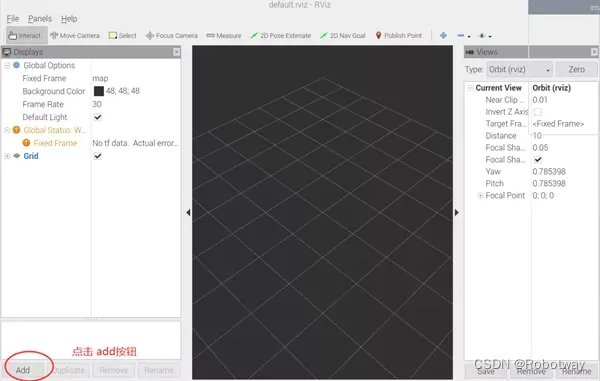
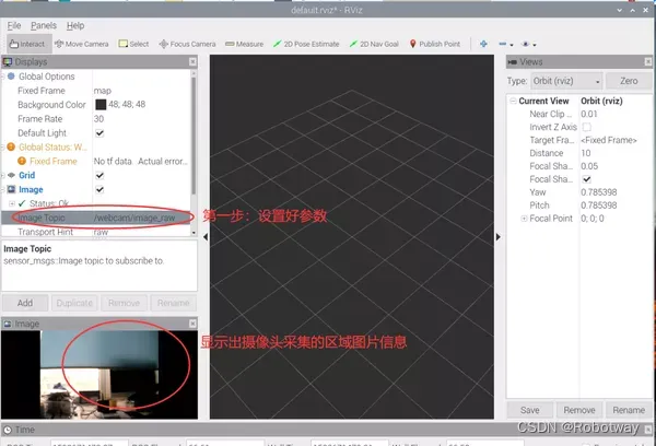
打开终端,输入roslaunch qr_detection qr_detection_experiment.launch命令(见下图),等待程序的运行启动界面。

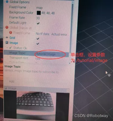
界面启动后,添加Image并设置其参数,设置成功后出现以下三幅图像画面。

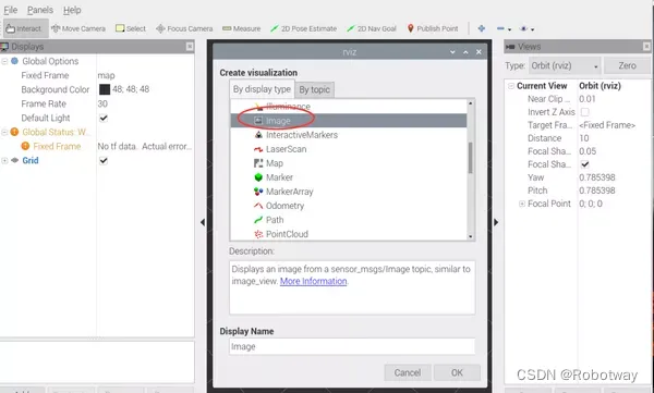

把QR code类型的二维码放置在摄像头下,稍后就会在界面上显示结果(如下图所示)。

2. 形状识别—识别圆形
实现思路
利用摄像头采集图片信息,识别圆形后显示出圆的中心坐标。
器材准备
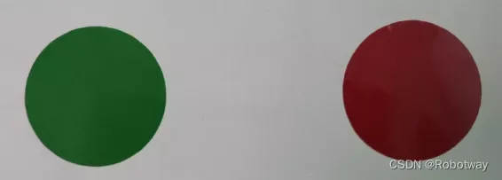
主要用到:摄像头、红色和绿色两种圆形图(如下图所示)。
操作步骤
第一步:连接电路,将摄像头与主机进行连接。(温馨提示:做实验时,大家可以灵活的把摄像头放置在圆形图片上方,以便于采集图形信息)
第二步:下载文末资料中的参考程序color_experiment_ws\src\shape_detection\scripts\shape_detection_victory.py:
#!/usr/bin/env python

#!coding=utf-8

import rospy

from sensor_msgs.msg import Image

import cv2

from cv_bridge import CvBridge

import numpy as np

#red,green,blue[h,s,v]

lower_blue=np.array([50,143,146])

upper_blue=np.array([124,255,255])

lower_red=np.array([0,200,55])

upper_red=np.array([10,255,130])

lower_green=np.array([40,43,46])

upper_green=np.array([77,255,255])

Video = cv2.VideoCapture(0)

ret = Video.set(3, 640)   # 设置帧宽

ret = Video.set(4, 480)   # 设置帧高

font = cv2.FONT_HERSHEY_SIMPLEX   # 设置字体样式

kernel = np.ones((5, 5), np.uint8)   # 卷积核

def areaCal(contour):

    area = 0

    for i in range(len(contour)):

        area += cv2.contourArea(contour[i])

    return area

def talker():

     pub = rospy.Publisher('/tutorial/image', Image, queue_size=1)

     rospy.init_node('talker', anonymous=True)

     rate = rospy.Rate(30)

     bridge = CvBridge()

     #Video = cv2.VideoCapture(1)

     while not rospy.is_shutdown():

         if Video.isOpened() is True:

           ret, frame = Video.read()

           gray = cv2.cvtColor(frame, cv2.COLOR_BGR2GRAY)   # 转换为灰色通道

           hsv = cv2.cvtColor(frame, cv2.COLOR_BGR2HSV)   # 转换为HSV空间

           mask = cv2.inRange(hsv, lower_red, upper_red)   # 设定掩膜取值范围   [消除噪声]

           #mask = cv2.inRange(hsv, lower_green, upper_green)   # 设定掩膜取值范围 [消除噪声]

           opening = cv2.morphologyEx(mask, cv2.MORPH_OPEN, kernel)   # 形态学开运算 [消除噪声]

           bila = cv2.bilateralFilter(mask, 10, 200, 200)   # 双边滤波消除噪声 [消除噪声]

           edges = cv2.Canny(opening, 50, 100)   # 边缘识别 [消除噪声]

           mask_green = cv2.inRange(hsv,lower_green,upper_green)

           opening_green = cv2.morphologyEx(mask_green, cv2.MORPH_OPEN, kernel)

           bila_green = cv2.bilateralFilter(mask_green, 10, 200, 200)

           edges_green = cv2.Canny(opening_green, 50, 100)

           images,contourss,hierarchvs = cv2.findContours(edges_green,cv2.RETR_TREE,cv2.CHAIN_APPROX_SIMPLE)

           image,contours,hierarchv = cv2.findContours(edges,cv2.RETR_TREE,cv2.CHAIN_APPROX_SIMPLE)

           print "area_red=",areaCal(contours),"area_green=",areaCal(contourss)

           if(areaCal(contours)>50):

             #circles = cv2.HoughCircles(edges, cv2.HOUGH_GRADIENT, 1, 100, param1=100, param2=20, minRadius=20, maxRadius=500)

             circles = cv2.HoughCircles(edges, cv2.HOUGH_GRADIENT, 1, 100, param1=100, param2=20, minRadius=0, maxRadius=0)

             if circles is not None:   # 如果识别出圆

               #print "I found the red circle"

               for circle in circles[0]:

                 x_red=int(circle[0])

                 y_red=int(circle[1])

                 r_red=int(circle[2])

                 cv2.circle(frame, (x_red, y_red), r_red, (0, 0, 255), 3)   # 标记圆

                 cv2.circle(frame, (x_red, y_red), 3, (255, 255, 0), -1)   # 标记圆心

                 text = 'circle' + 'x:   '+str(x_red)+' y:   '+str(y_red)

                 cv2.putText(frame, text, (10, 30), font, 1, (0, 255, 0), 2, cv2.LINE_AA, 0)   # 显示圆心位置

           if(areaCal(contourss)>1000):

             #circles = cv2.HoughCircles(edges, cv2.HOUGH_GRADIENT, 1, 100, param1=100, param2=20, minRadius=20, maxRadius=500)

             circles = cv2.HoughCircles(edges_green, cv2.HOUGH_GRADIENT, 1, 100, param1=100, param2=20, minRadius=0, maxRadius=0)

             if circles is not None:   # 如果识别出圆

               #print "I found the green circle"

               for circle in circles[0]:

                 x_red=int(circle[0])

                 y_red=int(circle[1])

                 r_red=int(circle[2])

                 cv2.circle(frame, (x_red, y_red), r_red, (0, 0, 255), 3)   # 标记圆

                 cv2.circle(frame, (x_red, y_red), 3, (255, 255, 0), -1)   # 标记圆心

                 text = 'circle' + 'x:   '+str(x_red)+' y:   '+str(y_red)

                 cv2.putText(frame, text, (10, 60), font, 1, (0, 255, 0), 2, cv2.LINE_AA, 0)   # 显示圆心位置

#cv2.drawContours(img,contours,-1,(0,0,255),3)

         cv2.waitKey(3)

         pub.publish(bridge.cv2_to_imgmsg(frame, "bgr8"))

         rate.sleep()

if __name__ == '__main__':

     try:

         talker()

     except rospy.ROSInterruptException:

pass第三步:运行程序并查看效果。
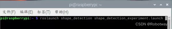
打开终端,输入roslaunch shape_detection shape_detection_experiment.launch 命令(见下图), 等待程序的运行启动界面。
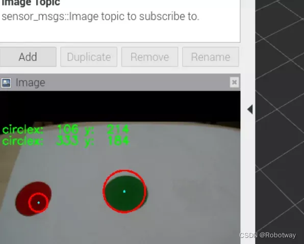
界面启动后,添加Image并设置其参数,设置成功后出现以下三幅图像画面。

放置待识别的圆形图(请把物品放置在摄像头可以采集到的区域),然后就可以在界面上看到识别结果。下图是分别识别红色圆形、蓝色圆形,并显示识别出圆心的中心坐标x、y的值。
3. 颜色识别(红绿蓝)
实现思路
摄像头采集红绿蓝的物品颜色后,利用开源视觉库进行识别,把结果显示在屏幕上。

颜色识别算法
RGB和HSV彩色模型
数字图像处理通常采用RGB(红、绿、蓝)和HSV(色调、饱和度、亮度)两种彩色模型,RGB虽然表示比较至直观,但R、G、B数值和色彩三属性并没有直接关系,模型通道并不能很好的反映出物体具体的颜色信息,而HSV模型更符合我们描述和解释颜色的方式,使用HSV的彩色描述会更加直观。
RGB和HSV的区别:
①. RGB模型
三维坐标:

RGB:三原色(Red, Green, Blue)
原点到白色顶点的中轴线是灰度线,r、g、b三分量相等,强度可以由三分量的向量表示。
用RGB来理解色彩、深浅、明暗变化:
色彩变化: 三个坐标轴RGB最大分量顶点与黄紫青YMC色顶点的连线
深浅变化:RGB顶点和CMY顶点到原点和白色顶点的中轴线的距离
明暗变化:中轴线的点的位置,到原点,就偏暗,到白色顶点就偏亮
②. HSV模型
倒锥形模型:

这个模型就是按色彩、深浅、明暗来描述的。
H是色彩
S是深浅, S = 0时,只有灰度
V是明暗,表示色彩的明亮程度,但与光强无直接联系。

③. RGB与HSV的联系
从上面的直观的理解,把RGB三维坐标的中轴线立起来,并扁化,就能形成HSV的锥形模型了。
但V与强度无直接关系,因为它只选取了RGB的一个最大分量。而RGB则能反映光照强度(或灰度)的变化。
v = max(r, g, b)
由RGB到HSV的转换:

④.HSV色彩范围

操作步骤
第一步:连接电路。将摄像头与主机进行连接。

第二步:下载文末资料中的参考程序color_experiment_ws\src\color_detection\scripts\color_test_one.py:
#!/usr/bin/env python

#!coding=utf-8

#write by leo at 2018.04.26

#function:

#1, Get live_video from the webcam.

#2, With ROS publish Image_info (to yolo and so on).

#3, Convert directly, don't need to save pic at local.

import rospy

from sensor_msgs.msg import Image

import cv2

import numpy as np

from cv_bridge import CvBridge, CvBridgeError

import sys

import time

cap = cv2.VideoCapture(0)

#lower_blue=np.array([50,143,146])

#upper_blue=np.array([124,255,255])

lower_blue=np.array([40,143,146])

upper_blue=np.array([124,255,255])

lower_red=np.array([0,200,55])

upper_red=np.array([10,255,130])

lower_green=np.array([40,43,46])

upper_green=np.array([77,255,255])

font = cv2.FONT_HERSHEY_SIMPLEX

def areaCal(contour):

    area = 0

    for i in range(len(contour)):

        area += cv2.contourArea(contour[i])

    return area

def webcamImagePub():

    # init ros_node

    rospy.init_node('webcam_puber', anonymous=True)

    # queue_size should be small in order to make it 'real_time'

    # or the node will pub the past_frame

    img_pub = rospy.Publisher('webcam/image_raw', Image, queue_size=2)

    rate = rospy.Rate(20) # 5hz

    # define picture to_down' coefficient of ratio

    scaling_factor = 0.5

    # the 'CVBridge' is a python_class, must have a instance.

    # That means "cv2_to_imgmsg() must be called with CvBridge instance"

    bridge = CvBridge()

    if not cap.isOpened():

        sys.stdout.write("Webcam is not available!")

        return -1

    count = 0

    # loop until press 'esc' or 'q'

    while not rospy.is_shutdown():

        # get a frame and show

        ret, frame = cap.read()

#       cv2.imshow('Capture', frame)

        # change to hsv model

        hsv = cv2.cvtColor(frame, cv2.COLOR_BGR2HSV)

        #cv2.imshow("imageHSV",hsv)

        # get mask

        mask = cv2.inRange(hsv, lower_blue, upper_blue)

#       cv2.imshow('Mask', mask)

        # detect blue

        res = cv2.bitwise_and(frame, frame, mask=mask)

#        cv2.imshow('Result', res)

#       cv2.imshow('SOURCE', frame)

        image,contours,hierarchv = cv2.findContours(mask,cv2.RETR_TREE,cv2.CHAIN_APPROX_SIMPLE)

        blue_area=areaCal(contours)

        hsvs = cv2.cvtColor(frame, cv2.COLOR_BGR2HSV)

        masks = cv2.inRange(hsvs, lower_red, upper_red)

        ress = cv2.bitwise_and(frame, frame, mask=masks)

        images,contourss,hierarchvs = cv2.findContours(masks,cv2.RETR_TREE,cv2.CHAIN_APPROX_SIMPLE)

        red_area=areaCal(contourss)

        hsvss = cv2.cvtColor(frame, cv2.COLOR_BGR2HSV)

        maskss = cv2.inRange(hsvss, lower_green, upper_green)

        resss = cv2.bitwise_and(frame, frame, mask=maskss)

        imagess,contoursss,hierarchvss = cv2.findContours(maskss,cv2.RETR_TREE,cv2.CHAIN_APPROX_SIMPLE)

        green_area=areaCal(contoursss)

        print "blue=",blue_area,"red=",red_area,"green=",green_area,"the color is blue"

        if(areaCal(contours)>300):

                #print("the color is blue")

                #print "blue=",blue_area,"red=",red_area,"green=",green_area,"the color is blue"

                text = 'the color is blue'

                cv2.putText(frame, text, (10, 30), font, 1, (255, 0, 0), 2, cv2.LINE_AA, 0)

        else :

                if(areaCal(contourss)>3500):

                        #print ("Thered",areaCal(contours))

                        #print "blue=",blue_area,"red=",red_area,"green=",green_area,"the color is blue red"

                        text = 'the color is red'

                        cv2.putText(frame, text, (10, 60), font, 1, (0, 0, 255), 2, cv2.LINE_AA, 0)

                else:

                        if(areaCal(contoursss)>3500):

                                #print "blue=",blue_area,"red=",red_area,"green=",green_area,"the color is blue green"

                                text = 'the color is green'

                                cv2.putText(frame, text, (10, 90), font, 1, (0, 255, 0), 2, cv2.LINE_AA, 0)

                        else:

                                qwer=0

        # resize the frame

        if ret:

            count = count + 1

        else:

            rospy.loginfo("Capturing image failed.")

        if count == 2:

            count = 0

            frame = cv2.resize(frame,None,fx=scaling_factor,fy=scaling_factor,interpolation=cv2.INTER_AREA)

            msg = bridge.cv2_to_imgmsg(frame, encoding="bgr8")

            img_pub.publish(msg)

        rate.sleep()

if __name__ == '__main__':

    try:

        webcamImagePub()

    except rospy.ROSInterruptException:

        pass

#    except IndexError:

#   pass

#    except VIDEOIOERROR:

#   pass

#    except Unabletostopthestream:

#   pass

    finally:

webcamImagePub()第三步:运行程序并查看效果。
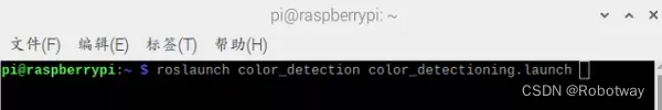
打开终端,输入roslaunch color_detection color_detectioning.launch命令(见下图), 等待程序的运行启动界面。
界面启动后,添加Image并设置其参数,设置成功后出现以下三幅图像画面。


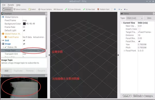
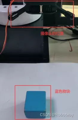
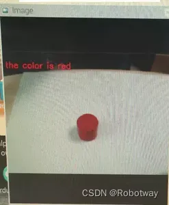
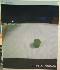
放置物品(请把物品放置在摄像头可以采集到的区域),然后摄像头开始识别颜色并在界面上显示识别结果。
下面以蓝色物品为例,当摄像头识别到蓝色物品后,在界面上显示结果(the color is blue)。
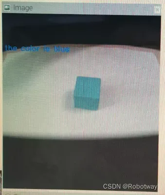
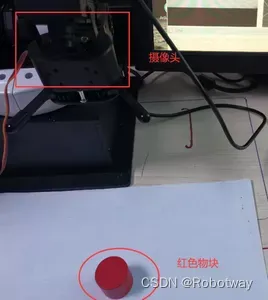
大家也可以试着去放置红色、绿色物品(识别结果见下面两幅图)。
4. 键盘控制运动
实现思路
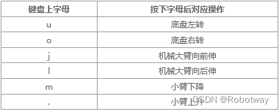
按下键盘上指定的键,实现底盘、大臂、小臂朝不同方向运动。
操作步骤
第一步:下载文末资料中的参考程序color_experiment_ws\src\visual_recognition\arduino_program\keyboard_control_arm\keyboard_control_arm.ino:
/*

_______________________________________________________________________________________________________________________________________________________

  【实验功能】

               ros中键盘控制机械臂运动。

  【实验接线】

               按照实验教程接线即可。

  【实验思路】

                上位机(树莓派)通过串口发布按键信息,下位机(Arduino)接收到信息后,进行简单数据处理,最后将处理后的数据

                 转换为机械臂相应的动作。

  【实验操作】

                按照实验教程接线。将该程序下载到arduino开发板,接着启动上位机(树莓派)程序。完成后,按下键盘不同的按键,观察

                机械臂动作。键盘指令包含:

                u:控制转台左转       o:控制转台右转

                j:控制大臂前伸       l:控制转台后缩

                m:控制小臂上抬       >:控制小臂下降

  create :2020.7.17   By Boris.yuan

  _________________________________________________________________________________________________________________________________________

*/

//DUE控制版需要启用USE_USBON或USE_NATIVE_USB,UNO不需要

//#define USE_USBCON          //PAOGRAMMING PORT

//#define USE_NATIVE_USB      //NATIVE USB PORT

#define ActionDelayTimes 1500

//#include <SoftwareSerial.h>

#include <Servo.h>

#include <ros.h>

#include <ros/time.h>

#include <geometry_msgs/Vector3.h>

#define mySerial Serial1

ros::NodeHandle   nh;

void XYRun(double vx, double vy, double w);

void messageCb( const geometry_msgs::Vector3& vel_cmd)   {

  XYSetVel(vel_cmd.x, vel_cmd.y, vel_cmd.z);

}

ros::Subscriber<geometry_msgs::Vector3> vel_cmd_sub("vel_cmd", &messageCb );

geometry_msgs::Vector3 pose_message;

ros::Publisher pose_feedback_pub("pose_feedback", &pose_message);

geometry_msgs::Vector3 vel_message;

ros::Publisher vel_feedback_pub("vel_feedback", &vel_message);

int servo_port[4] = {10, 11, 12, 13};//x,y,z,a

float value_init[4] = {88, 88, 96, 86};//x,y,z,a

const int kMessagePubRate = 5;

unsigned long message_pub_time = 0;

const int kReadMotorDeltaT = 5;

unsigned long position_read_time = 0;

float current_x = 0, current_y = 0, current_a = 0;

float current_vx = 0, current_vy = 0, current_va = 0;

float sudu = 0.87;

void setup()

{

  delay(1000);

  mySerial.begin(115200);

  Serial.begin(57600);

  Bus_servo_angle_init(); delay(1500);

  nh.initNode();

  nh.subscribe(vel_cmd_sub);

  nh.advertise(pose_feedback_pub);

  nh.advertise(vel_feedback_pub);

  position_read_time = millis();

  message_pub_time = millis();

}

void loop()

{

  if (millis() > position_read_time)

  {

    XYread();

    position_read_time += kReadMotorDeltaT;

  }

  if (millis() > message_pub_time)

  {

    pose_message.x = current_x;

    pose_message.y = current_y;

    pose_message.z = current_a;

    vel_message.x = current_vx;

    vel_message.y = current_vy;

    vel_message.z = current_va;

    pose_feedback_pub.publish(&pose_message);

    vel_feedback_pub.publish(&vel_message);

    message_pub_time += 1000.0 / kMessagePubRate;

  }

  nh.spinOnce();
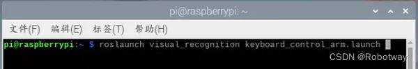
}第二步:打开终端,输入roslaunch visual_recognition keyboard_control_arm.launch 命令(见下图), 等待程序的运行启动界面。
第三步:尝试按下【u、o、j、l、m、.】观察运动,包括底盘左转、右转、大臂向前伸、大臂向后伸、小臂下降、小臂上升。(注意:字母均为小写;按键盘时,稍微有点间隔,给转动留时间)
5. 颜色识别与搬运
实现思路
摄像头识别不同颜色的物块后,机械爪开始抓取把其搬运到不同的区域。
操作步骤
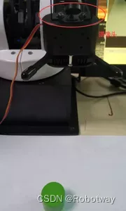
第一步:连接电路(见下图)。
第二步:下载文末资料中的参考程序color_experiment_ws\src\color_sorting\arduino_program\arm_driver\arm_driver.ino:
/*

-----------------------------------------------------------------------------------------------------------------

实验功能:【实现颜色分拣。】

实验思路:【上位机(即树莓派)检测到颜色(红色、蓝色),通过串口将发送不同颜色物体的字符串。下位机

            Arduino Mega2560接收到字符串后,执行相应的动作指令。本实验中,上位机检测到红色后,

            通过串口发送“reds”,当下位机Arduino接收到“reds”后,将红色物体向左边搬运。同理,

            上位机检测到蓝色后,串口发送“blues”,下位机接收到“blues”后,将物体搬运到机械臂的右侧。 】

实验操作:【将该程序下载到Arduino开发板后,按照教程启动上位机程序,将红色或者蓝色物体置于机械臂指定

                位置后,观察机械臂抓取不同颜色物体的动作是否与教程视频中相吻合。】

实验接线(主要接线):

            机械臂通信口-------------(机械臂)电控箱

            机械爪(舵机)---------------(执行器)电控箱

            其他线路按照教材图片连接。

Created 2020.7.16     By:Boris.yuan

-----------------------------------------------------------------------------------------------------------------

*/

#include <Servo.h>

#include <stdio.h>

#include <string.h>

#define CTL_BAUDRATE 115200 //总线舵机波特率

#define SERIAL_PRINTLN Serial1

#define SerialBaudrate 57600

String receive_string = "";

int catch_red_numbers=0;

int catch_blue_numbers=0;

unsigned long old_time = millis();

unsigned long new_time = millis();

void setup() {

  // put your setup code here, to run once:

  delay(1100);

  Serial.begin(SerialBaudrate);

  SERIAL_PRINTLN.begin(CTL_BAUDRATE);

  Bus_servo_angle_init();delay(2000);

//   Arm_Catch_Red_Object();delay(1000);

//   Arm_Catch_Blue_Object();delay(1000);

}

void loop() {

  // put your main code here, to run repeatedly:

  while(Serial.available()>0)

  {

    new_time = millis();

    receive_string=Serial.readStringUntil('\n');

    if(receive_string=="reds")

    {

      catch_red_numbers++;

      new_time = millis();

//      if(catch_red_numbers == 1)

//      {

//        //old_time = millis();

//        receive_string="";

//        //Arm_Catch_Red_Object();

//      }

//      if(catch_red_numbers == 2)

//      {

//        //old_time = millis();

//        receive_string="";

//        //Arm_Catch_Red_Object();

//      }

      if(catch_red_numbers == 1)

      {

        old_time = millis();receive_string="";

        Arm_Catch_Red_Object();

      }


      if(new_time-old_time>25000)

      {

        catch_red_numbers=0;

      }

    }

    if(receive_string=="blues")

    {

      catch_blue_numbers++;

      new_time = millis();

//      if(catch_blue_numbers == 3)

//      {

//        //old_time = millis();

//        receive_string="";

//        //Arm_Catch_Blue_Object();

//      }

//      if(catch_blue_numbers == 3)

//      {

//        //old_time = millis();

//        receive_string="";

//        //Arm_Catch_Blue_Object();

//      }

      if(catch_blue_numbers == 1)

      {

        old_time = millis();receive_string="";

        Arm_Catch_Blue_Object();

      }

      if(new_time-old_time>26000)

      {

        catch_blue_numbers=0;

      }

    }

    receive_string = "";

  }

}第三步:运行程序并查看效果。
打开终端(Alt+ctrl+T),输入roslaunch color_sorting open_camera_and_get_ImageTopic.launch 命令即可(见下图)。

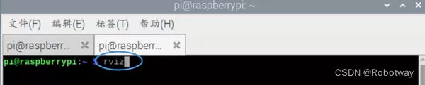
打开第二个终端(shift+ctrl+T),输入rviz命令,等待rviz界面启动。
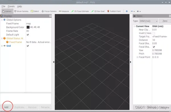
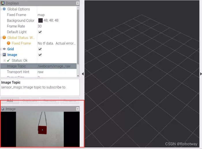
界面启动后,添加Image并设置其参数,设置成功后出现以下三幅图像画面。

放置物品(请把物品放置在摄像头可以采集到的区域),然后开始识别并进行搬运。下面以红色物品为例,当摄像头识别到红色物品后,机械爪把此物品搬运到一侧;当摄像头识别到蓝色物品时,把蓝色物品搬运到另一侧。这样就完成了按颜色识别物品并搬运的过程。
提示:颜色识别搬运时,待识别的物品周边尽量不要有过多的杂色,否则会误识别颜色。

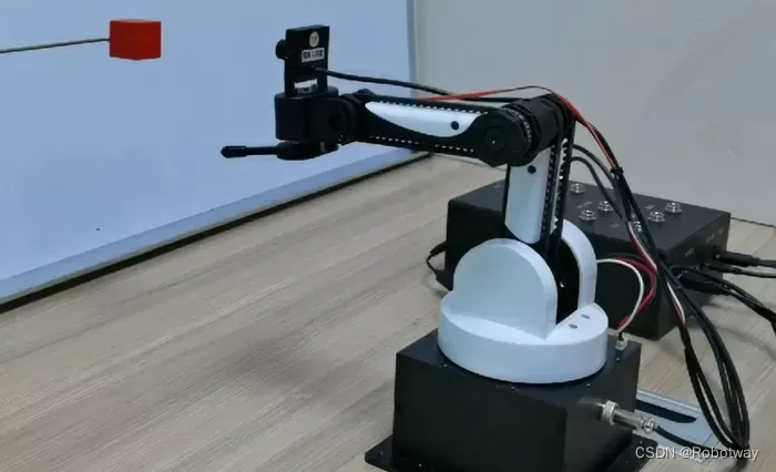
6. 颜色识别与追踪
实现思路
摄像头采集到物品颜色后,随着该颜色物品的运动而缓慢移动,实现追踪效果。
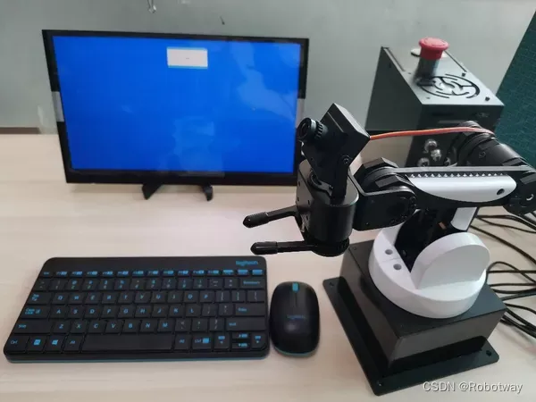
器材准备
本实验中需要用到的器材如下图所示,其中键盘、鼠标、红色物品可自行准备。


操作步骤
第一步:下载文末资料中的参考程序color_experiment_ws\src\color_tracking\arduino_program\color_tracking_Red_Things\color_tracking_Red_Things.ino:
/*

-----------------------------------------------------------------------------------------------------------------

实验功能:【实现颜色(红色)追踪】

实验思路:【上位机实现颜色检测(红色物体),检测到红色物体后,提取红色物体的中心点坐标想(x,y),之后通过

            检测红色物体的面积大小进而判断红色物体距离摄像头的远近(本实验通过比较检测红色物体面积的当前值

            与设定红色物体面积的标定值进行比较,进而判断红色物体距离摄像头的远近),判断结束后,会将红色

            物体的中心点坐标(即(x,y))及红色物体距离摄像头远近的数值(本实验使用的是字符串)通过串口发送

            给下位机Arduino Mega2560,下位机接收到数据后,机械臂按照该数据进行相应的动作。】

实验操作:【将该程序下载到Arduino开发板,之后按照教程启动树莓派例程,观察机械臂是否会跟随红色物体移动。】

实验接线(主要接线):

          机械臂通信口-------------(机械臂)电控箱

          机械爪(舵机)---------------(执行器)电控箱

          其他线路按照教材图片连接。

Created 2020.7.16     By:Boris.yuan

-----------------------------------------------------------------------------------------------------------------

*/

#include <Servo.h>

#include <stdio.h>

#include <string.h>

#define CTL_BAUDRATE 115200 //总线舵机波特率

#define SERIAL_PRINTLN Serial1

#define SerialBaudrate 57600

#define RGB_LED_NUMBERS 3

#define Bus_servo_Angle_inits 1500

String receive_string = "";

enum{RED=1,GREEN,BLUE,NONE_COLOR};

int catch_red_numbers=0;

int catch_blue_numbers=0;

unsigned long old_time = millis();

unsigned long new_time = millis();

int value_move[3]={1500,1500,1500};

int last_value[3]={0,0,0};

void setup() {

  // put your setup code here, to run once:

  delay(1100);

  Serial.begin(SerialBaudrate);

  SERIAL_PRINTLN.begin(CTL_BAUDRATE);

  Bus_servo_angle_init();delay(2000);

}

void loop() {

  while(Serial.available()>0)

  {

    new_time = millis();

    receive_string=Serial.readStringUntil('\n');

    if( (receive_string.length())<3 && (receive_string.length())>8 )

    {

      break;

    }

    else

    {

       int SpacePosition[2] = {0,0};

       int Data_one = 0;

       int Data_two = 0;

       int numbers_left=0 ,numbers_right=0;

       char num_left[32] = {};

       char num_right[32] = {};

       String x_data="";

       String y_data="";

       SpacePosition[0] = receive_string.indexOf('-');

      for(int j=0;j<SpacePosition[0];j++) {

         numbers_left++;

         if(receive_string[j] == 'c'){receive_string[j]='0';}

         x_data+=receive_string[j];

       }


       if(receive_string == "back")

       {

         value_move[1] -=3;

       }

       else if(receive_string == "forward")

       {

         value_move[1] +=3;

       }

       for(int k=SpacePosition[0]+1,m=0;k<receive_string.length();k++,m++) {

         numbers_right++;

         if(receive_string[k] == 'c'){receive_string[k]='0';}

         if(numbers_right>=4)

         {

           ;

         }

         else

         {

           y_data+=receive_string[k];

         }

       }

       Data_one=x_data.toInt();

       Data_two=y_data.toInt();

       if(Data_one !=0 )

       {

         last_value[0] = Data_one;

       }

       if(Data_one ==0)

       {

         Data_one = last_value[0];

       }


       if(Data_two !=0 )

       {

         last_value[2] = Data_two;

       }

       if(Data_two ==0)

       {

         Data_two = last_value[2];

       }

       if( Data_one<=280 ){value_move[0] +=2;}

       if( Data_one>=368 ){value_move[0] -=2;}

       if( Data_two<=230-50 ){value_move[2] +=2;}

       if( Data_two>=250+50 ){value_move[2] -=2;}

      ArmServoTos(value_move[0],value_move[1],value_move[2],50);//delay(100);

    }

    receive_string = "";

  }
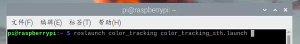
}第二步:打开终端(Alt+ctrl+T),输入roslaunch color_tracking color_tracking_sth.launch 命令即可,见下图。
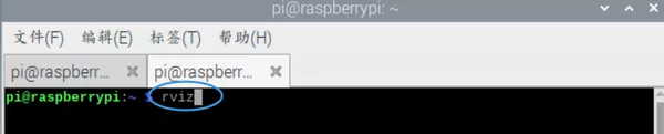
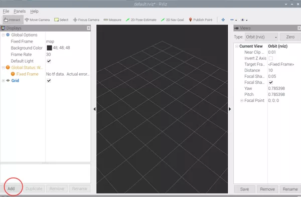
打开第二个终端(shift+ctrl+T),输入rviz命令,等待rviz界面启动。
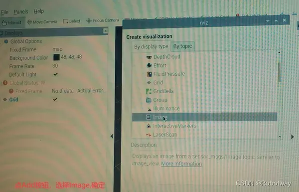
界面启动后,添加Image并设置其参数,设置成功后出现以下三幅图像画面。

第三步:放置物品(请把物品放置在摄像头可以采集到的区域),开始追踪。下面以红色物品为例,当摄像头识别到红色物品后,随着红色物品的运动缓慢移动,实现追踪效果。(注意:受硬件的影响,物品的移动速度要稍微慢一些)。
程序源代码资料详见 桌面级机械臂-应用设计