一开始,所有实验都是在神舟板上去完成,根本就没有发现RTC的问题。直到我们自己画板来后调试时,才发现STM32 RTC的外部时钟源存在问题。
这也算是STM32的一个鸡肋,对于LSE外部晶振太过于苛刻,手册上要求使用6pf,这个规格的晶振市场上太少,鱼龙混杂,中招的高手菜鸟不在少数。我们自己的板也是如此,几经波折,反反复复尝试使用不同的规格的晶振,替换外部的电容,电阻都没有能让这个32.768K的LSE起振。但是又需要有RTC来提供时间,考虑的方法主要有2种,第一采用外部RTC时钟芯片,如DS1302。第二是使用内部其它的时钟源来提供RTC时钟。毫无疑问,目前板已经制好,添加时钟芯片肯定造成板上布局更改,还得重新打板,这里采用了第二种方法。
查看STM32的手册上时钟树,如下:
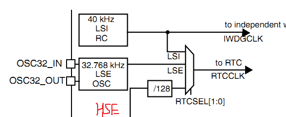
除去不能起振的外部低速LSE外,可供使用的只有LSI和HSE的128分频,LSI这个是内部的40KHz RC振荡器,频率在30~60KHz浮动,自然这个不能用于RTC计时,误差太大。
我们的板上配的是STM32F107这款芯片,外部高速晶振是25MHz的。128分频后频率为 25000000 / 128 = 195312.5 Hz,很显然这里也不能做到很精确,有小许误差。
然后设置RTC_PRL寄存器,写入195312这个分频值,便可以得到1Hz的频率。使用HSE作为RTC时钟,缺点就是无法在断开电源后使用后备电池进行供电,维持RTC的正常。下次需要上位机重新去设置时间。
代码大致如下:
-
void RTC_Configuration(void) -
{ -
u8 i = 0; -
/* Enable PWR and BKP clocks */ -
/* PWR时钟(电源控制)与BKP时钟(RTC后备寄存器)使能 */ -
RCC_APB1PeriphClockCmd(RCC_APB1Periph_PWR | RCC_APB1Periph_BKP, ENABLE); -
/* Allow access to BKP Domain */ -
/*使能RTC和后备寄存器访问 */ -
PWR_BackupAccessCmd(ENABLE); -
/* Reset Backup Domain */ -
/* 将外设BKP的全部寄存器重设为缺省值 */ -
BKP_DeInit(); -
/* Enable LSE */ -
/* 使能LSE(外部32.768KHz低速晶振)*/ -
RCC_LSEConfig(RCC_LSE_ON); -
/* Wait till LSE is ready */ -
/* 等待外部晶振震荡稳定输出 */ -
TIM5_Init_Query(CALC_TYPE_MS); //ms 级别 -
for (i = 0;i < 10;i++) //10次检测,如果LSE仍然没有起振,证明这玩意有问题,跳出循环 -
{ -
if (RCC_GetFlagStatus(RCC_FLAG_LSERDY) != RESET) -
break; -
TIM5_MS_CALC(1); //1ms延时 -
} -
//while (RCC_GetFlagStatus(RCC_FLAG_LSERDY) == RESET){} -
if (i == 10) -
{ -
//RCC->CSR |= 0x1; //开启内部低速晶振 -
//while (RCC_GetFlagStatus(RCC_FLAG_LSIRDY) == RESET); -
//RCC_RTCCLKConfig(RCC_RTCCLKSource_LSI); //使用LSI提供RTC时钟 -
//使用外部高速晶振 128分频 -
RCC_RTCCLKConfig(RCC_RTCCLKSource_HSE_Div128); -
}else -
{ -
/* Select LSE as RTC Clock Source */ -
/*使用外部32.768KHz晶振作为RTC时钟 */ -
RCC_RTCCLKConfig(RCC_RTCCLKSource_LSE); -
} -
/* Enable RTC Clock */ -
/* 使能 RTC 的时钟供给 */ -
RCC_RTCCLKCmd(ENABLE); -
/* Wait for RTC registers synchronization */ -
/*等待RTC寄存器同步 */ -
RTC_WaitForSynchro(); -
/* Wait until last write operation on RTC registers has finished */ -
/* 等待上一次对RTC寄存器的写操作完成 */ -
RTC_WaitForLastTask(); -
/* Enable the RTC Second */ -
/* 使能RTC的秒中断 */ -
RTC_ITConfig(RTC_IT_SEC, ENABLE); -
/* Wait until last write operation on RTC registers has finished */ -
/* 等待上一次对RTC寄存器的写操作完成 */ -
RTC_WaitForLastTask(); -
/* Set RTC prescaler: set RTC period to 1sec */ -
/* 32.768KHz晶振预分频值是32767,如果对精度要求很高可以修改此分频值来校准晶振 */ -
if (i != 10) //LSE不能正常 -
RTC_SetPrescaler(32767); /* RTC period = RTCCLK/RTC_PR = (32.768 KHz)/(32767+1) */ -
else -
RTC_SetPrescaler(195312); //25000000 / 128 = 195312.5,如果是8M / 128 = 62500,则这里应该填为62499 -
/* Wait until last write operation on RTC registers has finished */ -
/* 等待上一次对RTC寄存器的写操作完成 */ -
RTC_WaitForLastTask(); -
} -
void Init_RTC(void) -
{ -
/* 以下if...else.... if判断系统时间是否已经设置,判断RTC后备寄存器1的值 -
是否为事先写入的0XA5A5,如果不是,则说明RTC是第一次上电,需要配置RTC, -
提示用户通过串口更改系统时间,把实际时间转化为RTC计数值写入RTC寄存器, -
并修改后备寄存器1的值为0XA5A5。 -
else表示已经设置了系统时间,打印上次系统复位的原因,并使能RTC秒中断 -
*/ -
if (BKP_ReadBackupRegister(BKP_DR1) != RTC_SEQ_ID) -
{ -
/* Backup data register value is not correct or not yet programmed (when -
the first time the program is executed) */ -
/* RTC Configuration */ -
RTC_Configuration(); -
/* Adjust time by values entred by the user on the hyperterminal */ -
RTC_SetCounter(Time_Regulate(YEAR_BASE,01,01,0,0,0)); //2008-1-1 0:0:0 -
/* 修改后备寄存器1的值为0XA5A5 */ -
BKP_WriteBackupRegister(BKP_DR1, RTC_SEQ_ID); -
}else -
{ -
/* Check if the Power On Reset flag is set */ -
//RCC_GetFlagStatus(RCC_FLAG_PORRST) != RESET -
// printf("\r\n\n Power On Reset occurred...."); -
/* Check if the Pin Reset flag is set */ -
//else if (RCC_GetFlagStatus(RCC_FLAG_PINRST) != RESET) -
// printf("\r\n\n External Reset occurred...."); -
if (RCC_GetFlagStatus(RCC_FLAG_LSERDY) == RESET) -
{ -
//RCC->CSR |= 0x1; //开启内部低速晶振 -
//while (RCC_GetFlagStatus(RCC_FLAG_LSIRDY) == RESET); -
//RCC_RTCCLKConfig(RCC_RTCCLKSource_LSI); //使用LSI提供RTC时钟 -
//RCC_RTCCLKConfig(RCC_RTCCLKSource_HSE_Div128); -
RTC_Configuration(); -
} -
//printf("\r\n No need to configure RTC...."); -
/* Wait for RTC registers synchronization */ -
RTC_WaitForSynchro(); -
/* Enable the RTC Second */ -
RTC_ITConfig(RTC_IT_SEC, ENABLE); -
/* Wait until last write operation on RTC registers has finished */ -
RTC_WaitForLastTask(); -
} -
#ifdef RTCClockOutput_Enable -
/* Enable PWR and BKP clocks */ -
RCC_APB1PeriphClockCmd(RCC_APB1Periph_PWR | RCC_APB1Periph_BKP, ENABLE); -
/* Allow access to BKP Domain */ -
PWR_BackupAccessCmd(ENABLE); -
/* Disable the Tamper Pin */ -
BKP_TamperPinCmd(DISABLE); /* To output RTCCLK/64 on Tamper pin, the tamper -
functionality must be disabled */ -
/* Enable RTC Clock Output on Tamper Pin */ -
BKP_RTCOutputConfig(BKP_RTCOutputSource_CalibClock); -
#endif -
/* Clear reset flags */ -
RCC_ClearFlag(); -
}
实际测试,RTC效果还行,然后配合上位机隔一定的时间后同步时间基本上能够满足要求。
万恶的LSE晶振,这东西简直不能忍受......