转载自:(https://blog.csdn.net/xue_wenyuan/article/details/51533953).
介绍
我们已经知道,傅里叶变换是一种信号处理中的有力工具,可以帮助我们将图像从空域转换到频域,并提取到空域上不易提取的特征。但是经过傅里叶变换后,图像在不同位置的频度特征往往混合在一起,但是Gabor滤波器却可以抽取空间局部频度特征,是一种有效的纹理检测工具。
如何生成一个Gabor滤波器
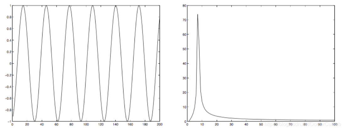
在二维空间中,使用一个三角函数(如正弦函数)与一个高斯函数叠加我们就得到了一个Gabor滤波器[1],如下图。

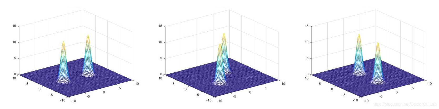
Gabor核函数
二维Gabor核函数由一个高斯函数和一个余弦函数相乘得出,其中 为参数。
在OpenCV中的getGaborKernel函数里需要传入的参数除了上述5个外,还需要传入卷积核的大小。
cv::Mat getGaborKernel(Size ksize, double sigma, double theta, double lambd, double gamma, double psi=CV_PI*0.5, int ktype=CV_64F );
参数
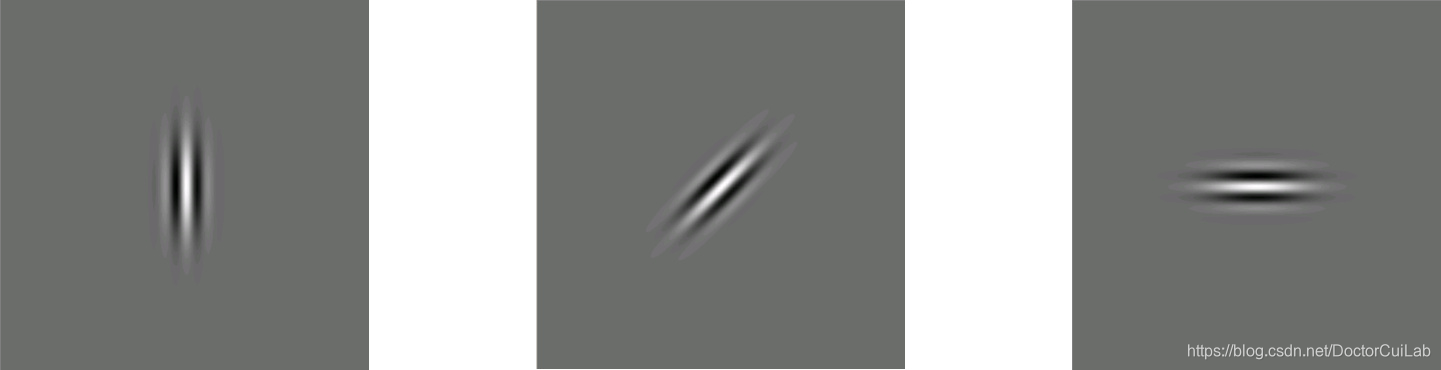
Orientation
表示Gabor滤波核中平行条带的方向,有效值为从0~360度的实数。
Phase offset
表示Gabor核函数中余弦函数的相位参数,有效值为-180度~180度,0度和180度对应的方程与原点对称,-90度和90度的方程分别于原点成中心对称,可两项直角坐标系中的余弦函数。
Aspect ratio
, 纵横比,更准确的应称为空间纵横比,表示Gabor滤波器的椭圆度。
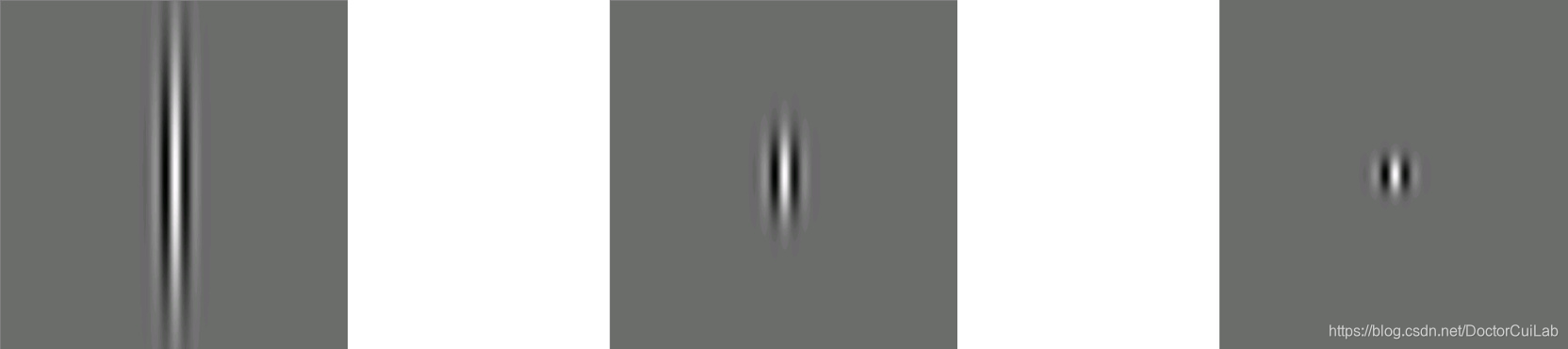
Wavelength
表示Gabor核函数中余弦函数的波长参数,有效值应大于2,以像素为单位。
The standard deviation
表示Gabor核函数中高斯函数的标准差,该参数决定了Gabor滤波核可接受区域的大小,
不能被直接指定,其值与
(Bandwidth)和
有关。
Bandwidth(
)表示高低频率之差。在实际选取Gabor滤波核中,我们会选取频域中半响应空间频度带宽(the half-response spatial frequency bandwidth),或者半峰量级(the half-peak magnitude),他们都指的是频域中Bandwidth/2的空间位置。
,
和
的关系如下:

演示
这里用一张程序运行动态图可以清楚的显示出Gabor滤波核随各个参数变化的情况。
如何设计Gabor滤波器来提取特征
为了充分利用Gabor滤波器的特点,我们必然需要设计不同方向,不同尺度的GaborL滤波器来提取特征,[2]中提到了如下策略来使滤波器尽量无重叠覆盖频域中的各个方向:
“Then the design strategy is to ensure that the half-peak magnitude support of the filter responses in the frequency spectrum touch each other .”
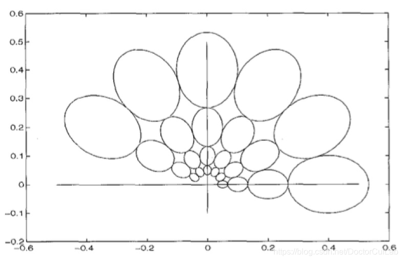
首先通过如下公式计算出
其中
分别表示滤波器的中心频度,及波长
的倒数,
为方向的数量,
为尺度的数量。
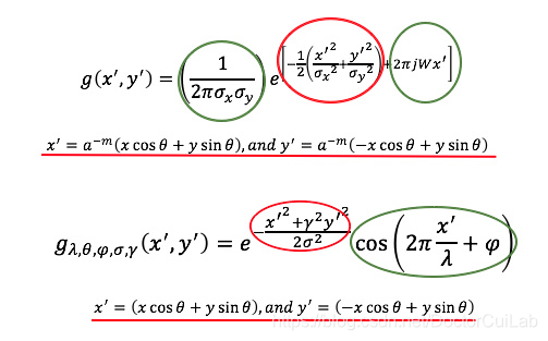
然后将上述结果带入下列Gabor核函数方程,从而求得Gabor卷积核上某点的值。其中
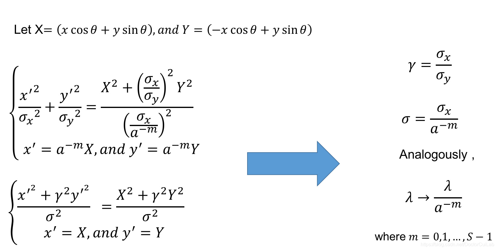
但是在OpenCV中的Gabor核函数采用式(1)的形式,因此我们需要对两种不同表达的Gabor核函数中的参数进行一些转换。比较两种表达式,不难看出,式(8)中的
是一个复数形式,可以分解成正余弦和的形式,与式(1)中的余弦函数部分相对应,式(8)最前端的部分为幅度。因此两种形式的主要区别在于高斯函数的指数以及
的表达不同。通过如下转换,就可以将式(8)中的参数转换成式(1)中的参数。
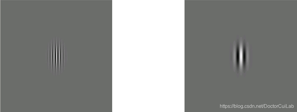
不同的卷积核(kernel size)大小对Gabor滤波核的影响
如果卷积核的边长小于波长,那么整个波形不能包括在卷积核中,使得波形边缘的滤波效果起不到作用。相反,如果如果卷积核的边长大于波长,则不会对滤波器产生什么影响。
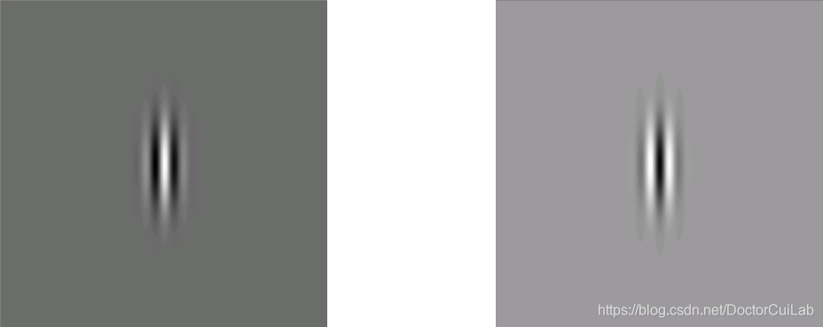
相位变化对Gabor滤波核的影响
通过相位变化可以改变滤波核中心点的波形,如果滤波核中心点正对波峰( ),则会对整张图像起到加强的作用,如果滤波核中心点正对波谷( ),则会对整张图像起到减弱的作用。我们应当避免滤波核中心点的波形位于零交叉点,因为这样我们可能会看不到滤波器的任何效果。
References
[1] Prasad V S N, Domke J. Gabor filter visualization[J]. J. Atmos. Sci, 2005, 13.
[2] Manjunath B S, Ma W Y. Texture features for browsing and retrieval of image data[J]. Pattern Analysis and Machine Intelligence, IEEE Transactions on, 1996, 18(8): 837-842.
[3] Movellan J R. Tutorial on Gabor filters[J]. Open Source Document, 2002.
[4] Celik T, Lee H K, Petznick A, et al. Bioimage informatics approach to automated meibomian gland analysis in infrared images of meibography[J]. Journal of optometry, 2013, 6(4): 194-204.
[5] Cheng E, Du L, Wu Y, et al. Discriminative vessel segmentation in retinal images by fusing context-aware hybrid features[J]. Machine Vision and Applications, 2014, 25(7): 1779-1792.
[6] Advances in Digital Document Processing and Retrieval[M]. World Scientific, 2013.
[7] 孔锐, 张冰. Gabor 滤波器参数设置[J]. 控制与决策, 2012, 27(8): 1277-1280.
Useful Web Sites
http://www.cs.rug.nl/~imaging/simplecell.html
http://www.juergenwiki.de/work/wiki/doku.php?id=public:gabor_filter
http://blog.163.com/hulin_feng/blog/static/9235253201231453211288/
帮助理解Gabor滤波器的有关文档,以及Gabor滤波器的可视化程序已经上传到Github.
以上内容编辑:崔健棣