Graphics Pipeline
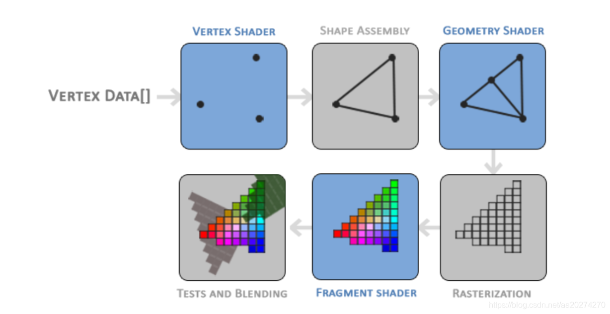
The first part of the pipeline is the vertex shader that takes as input a single vertex. The main purpose of the vertex shader is to transform 3D coordinates into different 3D coordinates (more on that later) and the vertex shader allows us to do some basic processing on the vertex attributes.
The primitive assembly stage takes as input all the vertices (or vertex if GL_POINTS is chosen) from the vertex shader that form a primitive and assembles all the point(s) in the primitive shape given; in this case a triangle.
The output of the primitive assembly stage is passed to the geometry shader. The geometry shader takes as input a collection of vertices that form a primitive and has the ability to generate other shapes by emitting new vertices to form new (or other) primitive(s). In this example case, it generates a second triangle out of the given shape.
The output of the geometry shader is then passed on to the rasterization stage where it maps the resulting primitive(s) to the corresponding pixels on the final screen, resulting in fragments for the fragment shader to use. Before the fragment shaders runs, clipping is performed. Clipping discards all fragments that are outside your view, increasing performance.
The main purpose of the fragment shader is to calculate the final color of a pixel and this is usually the stage where all the advanced OpenGL effects occur. Usually the fragment shader contains data about the 3D scene that it can use to calculate the final pixel color (like lights, shadows, color of the light and so on).
After all the corresponding color values have been determined, the final object will then pass through one more stage that we call the alpha test and blending stage. This stage checks the corresponding depth (and stencil) value (we’ll get to those later) of the fragment and uses those to check if the resulting fragment is in front or behind other objects and should be discarded accordingly. The stage also checks for alpha values (alpha values define the opacity of an object) and blends the objects accordingly. So even if a pixel output color is calculated in the fragment shader, the final pixel color could still be something entirely different when rendering multiple triangles.
Vertex input
To start drawing something we have to first give OpenGL some input vertex data. OpenGL is a 3D graphics library so all coordinates that we specify in OpenGL are in 3D (x, y and z coordinate). OpenGL doesn’t simply transform all your 3D coordinates to 2D pixels on your screen; OpenGL only processes 3D coordinates when they’re in a specific range between -1.0 and 1.0 on all 3 axes (x, y and z). All coordinates within this so called normalized device coordinates range will end up visible on your screen (and all coordinates outside this region won’t).
Normalized Device Coordinates (NDC)
Once your vertex coordinates have been processed in the vertex shader, they should be in normalized device coordinates which is a small space where the x, y andz values vary from -1.0 to 1.0. Any coordinates that fall outside this range will be discarded/clipped and won’t be visible on your screen. Below you can see the triangle we specified within normalized device coordinates (ignoring the z axis):

Unlike usual screen coordinates the positive y-axis points in the up-direction and the (0,0)coordinates are at the center of the graph, instead of top-left. Eventually you want all the (transformed) coordinates to end up in this coordinate space, otherwise they won’t be visible.
Your NDC coordinates will then be transformed to screen-space coordinates via the viewport transform using the data you provided with glViewport. The resulting screen-space coordi- nates are then transformed to fragments as inputs to your fragment shader.
We manage this memory via so called vertex buffer objects (VBO) that can store a large number of vertices in the GPU’s memory. The advantage of using those buffer objects is that we can send large batches of data all at once to the graphics card without having to send data a vertex a time. Sending data to the graphics card from the CPU is relatively slow, so wherever we can we try to send as much data as possible at once. Once the data is in the graphics card’s memory the vertex shader has almost instant access to the vertices making it extremely fast.
(总结:
1.
喂顶点数据给OpenGL去渲染的时候,OpenGL 需要的顶点数据是要在NDC空间中的,也就是,如果你的vertex shader 什么转换都不做,提供给VBO的顶点坐标,需要时NDC空间的,如果你提供给VBO的顶点数据并不是NDC空间的话,那么就需要在Shader中进行转换,把顶点变换到NDC空间)(注意,乘上 MVP 矩阵之后,会转换为 裁剪空间,那么硬件会帮我执行 透视除法,就可以从裁剪空间变成NDC空间)
2.
从CPU发送数据给 graphics card 是 比较慢的,所以,我们尽量一次发送足够多的数据。
Code
理解 VAO 和 VBO, EBO 关系:
    // build and compile our shader program
    // ------------------------------------
    // vertex shader
    int vertexShader = glCreateShader(GL_VERTEX_SHADER);
    glShaderSource(vertexShader, 1, &vertexShaderSource, NULL);
    glCompileShader(vertexShader);
    // check for shader compile errors
    int success;
    char infoLog[512];
    glGetShaderiv(vertexShader, GL_COMPILE_STATUS, &success);
    if (!success)
    {
        glGetShaderInfoLog(vertexShader, 512, NULL, infoLog);
        std::cout << "ERROR::SHADER::VERTEX::COMPILATION_FAILED\n" << infoLog << std::endl;
    }
    // fragment shader
    int fragmentShader = glCreateShader(GL_FRAGMENT_SHADER);
    glShaderSource(fragmentShader, 1, &fragmentShaderSource, NULL);
    glCompileShader(fragmentShader);
    // check for shader compile errors
    glGetShaderiv(fragmentShader, GL_COMPILE_STATUS, &success);
    if (!success)
    {
        glGetShaderInfoLog(fragmentShader, 512, NULL, infoLog);
        std::cout << "ERROR::SHADER::FRAGMENT::COMPILATION_FAILED\n" << infoLog << std::endl;
    }
    // link shaders
    int shaderProgram = glCreateProgram();
    glAttachShader(shaderProgram, vertexShader);
    glAttachShader(shaderProgram, fragmentShader);
    glLinkProgram(shaderProgram);
    // check for linking errors
    glGetProgramiv(shaderProgram, GL_LINK_STATUS, &success);
    if (!success) {
        glGetProgramInfoLog(shaderProgram, 512, NULL, infoLog);
        std::cout << "ERROR::SHADER::PROGRAM::LINKING_FAILED\n" << infoLog << std::endl;
    }
    glDeleteShader(vertexShader);
    glDeleteShader(fragmentShader);

    // set up vertex data (and buffer(s)) and configure vertex attributes
    // ------------------------------------------------------------------
    float vertices[] = {
         0.5f,  0.5f, 0.0f,  // top right
         0.5f, -0.5f, 0.0f,  // bottom right
        -0.5f, -0.5f, 0.0f,  // bottom left
        -0.5f,  0.5f, 0.0f   // top left
    };
    unsigned int indices[] = {  // note that we start from 0!
        0, 1, 3,  // first Triangle
        1, 2, 3   // second Triangle
    };
    unsigned int VBO, VAO, EBO;
    glGenVertexArrays(1, &VAO);
    glGenBuffers(1, &VBO);
    glGenBuffers(1, &EBO);
    // bind the Vertex Array Object first, then bind and set vertex buffer(s), and then configure vertex attributes(s).
    glBindVertexArray(VAO);

    glBindBuffer(GL_ARRAY_BUFFER, VBO);
    glBufferData(GL_ARRAY_BUFFER, sizeof(vertices), vertices, GL_STATIC_DRAW);

    glBindBuffer(GL_ELEMENT_ARRAY_BUFFER, EBO);
    glBufferData(GL_ELEMENT_ARRAY_BUFFER, sizeof(indices), indices, GL_STATIC_DRAW);

    glVertexAttribPointer(0, 3, GL_FLOAT, GL_FALSE, 3 * sizeof(float), (void*)0);
    glEnableVertexAttribArray(0);

    // note that this is allowed, the call to glVertexAttribPointer registered VBO as the vertex attribute's bound vertex buffer object so afterwards we can safely unbind
    glBindBuffer(GL_ARRAY_BUFFER, 0);

    // remember: do NOT unbind the EBO while a VAO is active as the bound element buffer object IS stored in the VAO; keep the EBO bound.
    //glBindBuffer(GL_ELEMENT_ARRAY_BUFFER, 0);

    // You can unbind the VAO afterwards so other VAO calls won't accidentally modify this VAO, but this rarely happens. Modifying other
    // VAOs requires a call to glBindVertexArray anyways so we generally don't unbind VAOs (nor VBOs) when it's not directly necessary.
    glBindVertexArray(0);


    // uncomment this call to draw in wireframe polygons.
    //glPolygonMode(GL_FRONT_AND_BACK, GL_LINE);

    // render loop
    // -----------
    while (!glfwWindowShouldClose(window))
    {
        // input
        // -----
        processInput(window);

        // render
        // ------
        glClearColor(0.2f, 0.3f, 0.3f, 1.0f);
        glClear(GL_COLOR_BUFFER_BIT);

        // draw our first triangle
        glUseProgram(shaderProgram);
        glBindVertexArray(VAO); // seeing as we only have a single VAO there's no need to bind it every time, but we'll do so to keep things a bit more organized
        //glDrawArrays(GL_TRIANGLES, 0, 6);
        glDrawElements(GL_TRIANGLES, 6, GL_UNSIGNED_INT, 0);
        // glBindVertexArray(0); // no need to unbind it every time

        // glfw: swap buffers and poll IO events (keys pressed/released, mouse moved etc.)
        // -------------------------------------------------------------------------------
        glfwSwapBuffers(window);
        glfwPollEvents();
    }

    // optional: de-allocate all resources once they've outlived their purpose:
    // ------------------------------------------------------------------------
    glDeleteVertexArrays(1, &VAO);
    glDeleteBuffers(1, &VBO);
    glDeleteBuffers(1, &EBO);
细节:
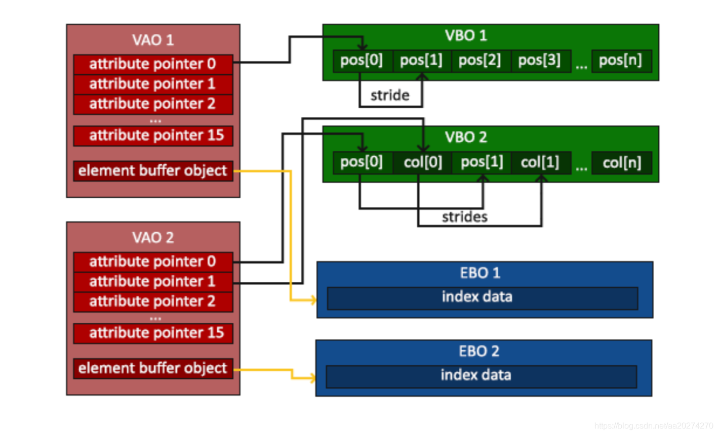
1. 先生成 VAO,VBO,EBO。
2. 绑定 VAO,
glBindVertexArray(VAO);
3. 把 VBO和 EBO 和VAO进行绑定,VBO和EBO 填充数据
glBindBuffer(GL_ARRAY_BUFFER, VBO);
glBufferData(GL_ARRAY_BUFFER, sizeof(vertices), vertices, GL_STATIC_DRAW);

glBindBuffer(GL_ELEMENT_ARRAY_BUFFER, EBO);
glBufferData(GL_ELEMENT_ARRAY_BUFFER, sizeof(indices), indices, GL_STATIC_DRAW);
4. VBO的数据与Shader 中的attribute 进行绑定
glVertexAttribPointer(0, 3, GL_FLOAT, GL_FALSE, 3 * sizeof(float), (void*)0);
glEnableVertexAttribArray(0);
5. 解绑
glBindBuffer(GL_ARRAY_BUFFER, 0);
glBindVertexArray(0);
6.在渲染之前,先绑定VAO
glBindVertexArray(VAO);
glDrawElements(GL_TRIANGLES, 6, GL_UNSIGNED_INT, 0);