ADXL345连接指南
原版地址:https://learn.sparkfun.com/tutorials/adxl345-hookup-guide
资料下载:https://download.csdn.net/download/acktomas/11069138
文章目录
参考资料及样例:
- 关于MPU6050的数据获取、分析与处理: https://blog.csdn.net/acktomas/article/details/89087174
- MPU-60X0datasheet中文版和英文版V4.0: https://download.csdn.net/download/acktomas/11096370
- 【译】使用Arduino+MPU6050传感器DIY倾角仪 https://www.yiboard.com/thread-805-1-1.html
- [极客工坊]【翻译】加速度计和陀螺仪指南: https://blog.csdn.net/acktomas/article/details/88073345
- 【翻译】关于ADXL345连接指南: https://blog.csdn.net/acktomas/article/details/88870325
- 关于加速度计收藏的几篇文章:https://blog.csdn.net/acktomas/article/details/88880075
1. 介绍
该ADXL345是一种小型,薄,低功耗,3轴MEMS加速度计具有高分辨率(13位)测量高达+/- 16g 数字输出数据格式为16位二进制补码,可通过SPI(3线或4线)或I2C数字接口访问。

该连接指南将使用SparkFun ADXL345 Arduino库和示例代码探索ADXL345的各种功能。首先,让我们来看看这款小而强大的加速度计的背景知识。
当我们逐步完成Hook Up指南时,您会发现手头有ADXL345数据表非常有用。
**注意:**如果您计划在I2C模式下使用ADXL345,则无需从上面的列表中购买逻辑电平转换器。
建议阅读
如果您不确定该产品是否适合您的需求,请查看Accelerometer,Gyro和IMU购买指南。在此过程中可能有用的一些其他资源,特别是如果您刚刚开始,可以在此处找到:
相关补充:
- 如何焊接:通孔焊接
本教程涵盖了有关通孔焊接所需了解的所有内容。 - 如何剥线,压接和使用电线。
- 加速度计基础知识
快速介绍加速度计,它们的工作原理以及它们的使用原因。 - I2C
I2C介绍,是当今使用的主要嵌入式通信协议之一。
2. 硬件概述
2.1特性
- 电源电压:2.0 - 3.6 VDC
- 超低功耗:测量模式下低至23 uA,待机模式下为2.5u时为0.1uA
- SPI或I2C通信
- 单击/双击检测
- 活动/不活动感应
- 自由落体检测
哇!最后三个是什么?!是的,ADXL345具有特殊的感应能力!单击和双击检测可检测何时发生单个或两个同时发生的加速事件。活动和不活动感测检测是否存在运动。自由落体感应将所有轴上的加速度与阈值进行比较,以了解设备是否在下降。触发活动,自由落体和单击/双击事件的所有阈值级别都是用户设置的级别。这些功能也可以映射到两个中断输出引脚中的一个。集成的,正在申请专利的32级先进先出(FIFO)缓冲器可用于存储数据,以最大限度地减少主机处理器的干预。
ADXL345非常适合测量倾斜传感应用中的静态重力加速度,以及运动或冲击引起的动态加速度。其高分辨率(4 mg / LSB)可测量小于1.0°的倾角变化。此外,低功耗模式可实现基于动态的智能电源管理,具有阈值检测功能和极低功耗的主动加速度测量功能。
2.2 应用
- 手机
- 医疗仪器
- 游戏和指点设备
- 工业仪器仪表
- 个人导航设备
- 硬盘驱动器(HDD)保护
2.3 引脚功能
下面您可以参考ADXL345分线板和引脚功能。

Breakout Board Pin Function Descriptions:分线板引脚功能描述
| 助记符 | 描述 |
|---|---|
| GND | 该引脚必须接地 |
| VCC | 电源电压 |
| CS | 芯片选择 |
| INT1 | 中断1输出 |
| INT2 | 中断2输出 |
| SDO | 串行数据输出(SPI 4线)/ I2C地址选择 |
| SDA / SDI / SDIO | 串行数据I2C /串行数据输入(SPI 4线)/串行数据输入和输出(SPI 3线) |
| SCL / SCLK | 串行通信时钟 |
2.3 部件
利用ADXL345,可以使用I2C和SPI数字通信。在这两种情况下,ADXL345都作为从器件工作。
注意:将ADXL345接口连接到Arduino(或兼容板)时可能存在的问题是,如果您使用的是具有松散连接的跳线的面包板,则可能会导致数据损坏。确保你的连接牢固,你应该没事。
3. SPI通信
首先,我们将介绍如何将Arduino(或兼容的板,如SparkFun的RedBoard)连接到ADXL345分线板以进行SPI通信。
在SPI模式下,CS引脚由总线主控制器控制。对于SPI,可以使用3线或4线配置。
注:使用3线SPI时,建议将SDO引脚上拉至VDD I/O或通过10kΩ电阻下拉至GND。有关其他信息,请参阅ADXL345添加链接描述数据手册的第15页。
以下是描述Arduino上的哪些引脚应连接到加速度计上用于SPI 4线通信的引脚的表格。
| Arduino Pin | ADXL345引脚 |
|---|---|
| GND | GND |
| 3V3 | VCC |
| 10 | CS |
| 12 | SDO |
| 11 | SDA |
| 13 | SCL |
这是一个接线图,可帮助您将其连接起来进行SPI 4线通信。

当心!如果使用5V Arduino,例如SparkFun RedBoard或Arduino Uno,则需要使用逻辑电平转换器来保护ADXL345的3 / 3V容差引脚(如上图所示)。如果使用3.3V Arduino,例如Arduino Pro或Pro Mini 3.3V / 8MHz,则无需进行逻辑电平转换。
4. I2C通信
现在,我们来看看如何将Arduino(或兼容的板,如SparkFun的RedBoard)连接到ADXL345分线板进行I2C通信。
如果CS引脚连接为高电平,则使能I2C模式。如果CS引脚未连接,则没有默认模式,因此应始终将其连接到高电平或由外部控制器驱动。
Note: If other devices are connected to the same I2C bus, the nominal operating voltage level of those other devices cannot exceed VDD I/O by more than 0.3 V. External pull-up resistors are necessary for proper I2C operation. Used in this connection diagram are two 4.7 kΩ resistors. Please refer to page 18 of the ADXL345 Datasheet for additional information.
翻译:注:如果其他器件连接到同一I2C总线,则其他器件的标称工作电压电平不能超过VDD I/O 0.3 V以上。外部上拉电阻是正确I2C操作所必需的。 在此连接图中使用两个4.7kΩ电阻。 有关其他信息,请参阅ADXL345数据手册的第18页。
The following is a table describing which pins on the Arduino should be connected to the pins on the accelerometer for I2C communication.
| Arduino Pin | ADXL345 Pin |
|---|---|
| GND | GND |
| 3V3 | VCC |
| 3V3 | CS |
| GND | SDO |
| A4 | SDA |
| A5 | SCL |
Here is a wiring connection diagram to aid you in hooking it up for I2C communication.
翻译:这是一个接线图,可以帮助您将其连接起来进行I2C通信。

不使用SparkFun RedBoard或Arduino Uno?下面的参考表显示了双线接口(TWI)引脚位于不同和较旧的Arduino板上的位置。
| 板 | I2C / TWI引脚 |
|---|---|
| SparkFun Red,Uno,以太网 | A4(SDA),A5(SCL) |
| Mega2560 | 20(SDA),21(SCL) |
| Leonardo | 2(SDA),3(SCL) |
| Due | 20 (SDA),21(SCL),SDA1,SCL1 |
5. SparkFun ADXL345库
The most exciting part of the Hookup Guide is the SparkFun ADXL345 library we’ve put together for you. Now, you not only have the ability to customize your sensing functions but also switch easily back and forth between I2C and SPI communication.
To get started, you can download the library here along with example code. For the most up-to-date code visit the SparkFun ADXL345 Arduino Library Repo.
翻译:Hookup指南中最激动人心的部分是我们为您准备的SparkFun ADXL345库。现在,您不仅可以自定义传感功能,还可以在I2C和SPI通信之间轻松切换。
要开始使用,您可以在此处下载库以及示例代码。有关最新代码,请访问SparkFun ADXL345 Arduino Library Repo。
5.1 下载的文件包括:
库.cpp和.h文件
- Arduino Sketch:ADXL345校准示例
- Arduino Sketch:ADXL345示例
- Arduino Sketch:SparkFun Baby Blynk Monitor Thing示例
- README.md
- keywords.txt
在我们能够使用示例代码之前,我们需要将SparkFun_ADXL345_Library文件夹放入Arduino库中。如果您不知道它的位置,通常可以在此处找到它: - PC:我的文档> Arduino> Libraries
- Mac :(主目录)>文档> Arduino> libraries
- Linux :(主目录)> Sketchbook> Libraries
有关安装库的帮助,请查看我们的安装Arduino库教程。
5.2 使用SparkFun ADXL345库
一旦安装了SparkFun ADXL345库,就可以把SparkFun_ADXL345_Example.ino在Arduino IDE中打开它。
确保已下载并安装了Arduino Software IDE,以便打开示例代码并对电路板进行编程。
5.2.1 示例代码
现在您已打开示例草图,让我们看看我们可以自定义ADXL345的所有方法。
5.2.1.1 SPI还是I2C?
第一个重要的选择是在COMMUNICATION SECTION。在这里您可以让库知道您是否已经为SPI或I2C通信设置了硬件。
/*********** COMMUNICATION SELECTION ***********/
/*    Comment Out The One You Are Not Using    */
ADXL345 adxl = ADXL345(10);           // USE FOR SPI COMMUNICATION, ADXL345(CS_PIN);
//ADXL345 adxl = ADXL345();             // USE FOR I2C COMMUNICATION
请务必注释掉//您未使用的代码行。默认情况下,代码使用SPI通信。
5.2.1.2 setup
示例代码中最复杂的部分是该void setup()部分。您可以在此处配置设置和感应功能阈值。
/******************** SETUP ********************/
/*          Configure ADXL345 Settings         */
void setup(){

Serial.begin(9600);                 // Start the serial terminal
Serial.println("SparkFun ADXL345 Accelerometer Hook Up Guide Example");
Serial.println();

adxl.powerOn();                     // Power on the ADXL345

adxl.setRangeSetting(16);           // Give the range settings
                                    // Accepted values are 2g, 4g, 8g or 16g
                                    // Higher Values = Wider Measurement Range
                                    // Lower Values = Greater Sensitivity

adxl.setSpiBit(0);                  // Configure the device to be in 4 wire SPI mode when set to '0' or 3 wire SPI mode when set to 1
                                    // Default: Set to 1
                                    // SPI pins on the ATMega328: 11, 12 and 13 as reference in SPI Library

adxl.setActivityXYZ(1, 0, 0);       // Set to activate movement detection in the axes "adxl.setActivityXYZ(X, Y, Z);" (1 == ON, 0 == OFF)
adxl.setActivityThreshold(75);      // 62.5mg per increment   // Set activity   // Inactivity thresholds (0-255)

adxl.setInactivityXYZ(1, 0, 0);     // Set to detect inactivity in all the axes "adxl.setInactivityXYZ(X, Y, Z);" (1 == ON, 0 == OFF)
adxl.setInactivityThreshold(75);    // 62.5mg per increment   // Set inactivity // Inactivity thresholds (0-255)
adxl.setTimeInactivity(10);         // How many seconds of no activity is inactive?

adxl.setTapDetectionOnXYZ(0, 0, 1); // Detect taps in the directions turned ON "adxl.setTapDetectionOnX(X, Y, Z);" (1 == ON, 0 == OFF)

// Set values for what is considered a TAP and what is a DOUBLE TAP (0-255)
adxl.setTapThreshold(50);           // 62.5 mg per increment
adxl.setTapDuration(15);            // 625 μs per increment
adxl.setDoubleTapLatency(80);       // 1.25 ms per increment
adxl.setDoubleTapWindow(200);       // 1.25 ms per increment

// Set values for what is considered FREE FALL (0-255)
adxl.setFreeFallThreshold(7);       // (5 - 9) recommended - 62.5mg per increment
adxl.setFreeFallDuration(30);       // (20 - 70) recommended - 5ms per increment

// Setting all interupts to take place on INT1 pin
//adxl.setImportantInterruptMapping(1, 1, 1, 1, 1);     // Sets "adxl.setEveryInterruptMapping(single tap, double tap, free fall, activity, inactivity);"
                                                        // Accepts only 1 or 2 values for pins INT1 and INT2. This chooses the pin on the ADXL345 to use for Interrupts.
                                                        // This library may have a problem using INT2 pin. Default to INT1 pin.

// Turn on Interrupts for each mode (1 == ON, 0 == OFF)
adxl.InactivityINT(1);
adxl.ActivityINT(1);
adxl.FreeFallINT(1);
adxl.doubleTapINT(1);
adxl.singleTapINT(1);

//attachInterrupt(digitalPinToInterrupt(interruptPin), ADXL_ISR, RISING);   // Attach Interrupt

}
这些评论可以帮助指导您了解每个功能的作用以及建议的范围,以保持在适用的范围内。有关传感功能和中断的更多详细信息,请参见ADXL345数据表。
5.2.1.3 主要代码
主要的示例代码保持非常简单。它不仅关注读取加速度计值,还关注是否发生了任何中断。
/****************** MAIN CODE ******************/
/*     Accelerometer Readings and Interrupt    */
void loop(){

// Accelerometer Readings
int x,y,z;
adxl.readAccel(&x, &y, &z);         // Read the accelerometer values and store them in variables declared above x,y,z

// Output Results to Serial
/* UNCOMMENT TO VIEW X Y Z ACCELEROMETER VALUES */
//Serial.print(x);
//Serial.print(", ");
//Serial.print(y);
//Serial.print(", ");
//Serial.println(z);

ADXL_ISR();
// You may also choose to avoid using interrupts and simply run the functions within ADXL_ISR();
//  and place it within the loop instead.
// This may come in handy when it doesn't matter when the action occurs.

}
目前,草图仅向串行监视器输出自由落体检测,不活动/活动以及单/双击检测。
要将测量的加速度计值打印到串行监视器,请记住取消注释以下部分,如下所示:
// Output Results to Serial
/* UNCOMMENT TO VIEW X Y Z ACCELEROMETER VALUES */
Serial.print(x);
Serial.print(", ");
Serial.print(y);
Serial.print(", ");
Serial.println(z);
5.2.1.4 串行监视器输出
让我们看看它在行动!转到Arduino IDE上的Tools,设置电路板和端口,并将SparkFun_ADXL345_Example.ino草图上传到Arduino或兼容板。如果您在上传草图时需要进一步的帮助,这可能会有所帮助:上传草图。
以下两个串行监视器输出是您应该期望的,无论您是否已显示加速度计值的显示。
加速度计值排除
这是触发传感功能时输出的样子。

包括加速度计值
这是您在取消注释X,Y和Z Serial.print()代码行时应该看到的数据。此外,请记住,您仍然会看到触发传感功能的时间,它可能更难以捕获数据流。
6. 校准
您可以使用的另一个草图是SparkFun_ADXL345_Calibration.ino。只要您的应用程序需要对设备进行精确校准,这将非常有用。
6.1 校准方法
精确的校准方法是每轴使用两个点。在我们的例子中,我们有一个三轴设计,因此,我们感兴趣的是六点。在数据表和示例草图中,您将注意到g范围的引用,其可接受的值为2g,4g,8g或16g。1g相当于作用在地球表面静止物体上的重力。可以以重力为单位测量相对于重力的加速度。
ADI公司的应用笔记是一个很好的资源:使用加速度计进行倾角传感
6.2 校准示例草图
以下是校准示例草图的外观:
#include <SparkFun_ADXL345.h>

/*********** COMMUNICATION SELECTION ***********/
/*    Comment Out The One You Are Not Using    */
//ADXL345 adxl = ADXL345(10);           // Use when you want to use Hardware SPI, ADXL345(CS_PIN);
ADXL345 adxl = ADXL345();             // Use when you need I2C

/****************** VARIABLES ******************/
/*                                             */
int AccelMinX = 0;
int AccelMaxX = 0;
int AccelMinY = 0;
int AccelMaxY = 0;
int AccelMinZ = 0;
int AccelMaxZ = 0;

int accX = 0;
int accY = 0;
int accZ = 0;

int pitch = 0;
int roll = 0;

/************** DEFINED VARIABLES **************/
/*                                             */
#define offsetX   0       // OFFSET values
#define offsetY   0
#define offsetZ   0

#define gainX     1     // GAIN factors
#define gainY     1
#define gainZ     1

/******************** SETUP ********************/
/*          Configure ADXL345 Settings         */
void setup()
{
  Serial.begin(9600);                 // Start the serial terminal
  Serial.println("SparkFun ADXL345 Accelerometer Breakout Calibration");
  Serial.println();

  adxl.powerOn();                     // Power on the ADXL345

  adxl.setRangeSetting(2);           // Give the range settings
  // Accepted values are 2g, 4g, 8g or 16g
  // Higher Values = Wider Measurement Range
  // Lower Values = Greater Sensitivity

  adxl.setSpiBit(0);                // Configure the device to be in 4 wire SPI mode when set to '0' or 3 wire SPI mode when set to 1
  // It is set to 1 by Default.
  // SPI pins on the ATMega328 as reference in SPI Library are 11, 12, and 13

}

/****************** MAIN CODE ******************/
/*  Accelerometer Readings and Min/Max Values  */
void loop()
{
  Serial.println("Send any character to display values.");
  while (!Serial.available()) {}      // Waiting for character to be sent to Serial
  Serial.println();

  // Get the Accelerometer Readings
  int x, y, z;                        // init variables hold results
  adxl.readAccel(&x, &y, &z);         // Read the accelerometer values and store them in variables declared above x,y,z

  if (x < AccelMinX) AccelMinX = x;
  if (x > AccelMaxX) AccelMaxX = x;

  if (y < AccelMinY) AccelMinY = y;
  if (y > AccelMaxY) AccelMaxY = y;

  if (z < AccelMinZ) AccelMinZ = z;
  if (z > AccelMaxZ) AccelMaxZ = z;

  Serial.print("Accel Minimums: "); Serial.print(AccelMinX); Serial.print("  "); Serial.print(AccelMinY); Serial.print("  "); Serial.print(AccelMinZ); Serial.println();
  Serial.print("Accel Maximums: "); Serial.print(AccelMaxX); Serial.print("  "); Serial.print(AccelMaxY); Serial.print("  "); Serial.print(AccelMaxZ); Serial.println();
  Serial.println();


  /* Note: Must perform offset and gain calculations prior to seeing updated results
    /  Refer to SparkFun ADXL345 Hook Up Guide: https://learn.sparkfun.com/tutorials/adxl345-hookup-guide
    /  offsetAxis = 0.5 * (Acel+1g + Accel-1g)
    /  gainAxis = 0.5 * ((Acel+1g - Accel-1g)/1g) */

  // UNCOMMENT SECTION TO VIEW NEW VALUES
  //accX = (x - offsetX)/gainX;         // Calculating New Values for X, Y and Z
  //accY = (y - offsetY)/gainY;
  //accZ = (z - offsetZ)/gainZ;

  //Serial.print("New Calibrated Values: "); Serial.print(accX); Serial.print("  "); Serial.print(accY); Serial.print("  "); Serial.print(accZ);
  //Serial.println();

  while (Serial.available())
  {
    Serial.read();                    // Clear buffer
  }
}
主代码将读取您的加速度计最大值和最小值。通过这些值,我们将能够计算偏移值和增益因子,为我们提供新的校准加速度计读数。我们将在一分钟内详细讨论这些计算的公式。
6.4 安装加速度计
在进行这些测量之前,我们希望安装的加速度计的Z轴平行于向上方向。例如,如果我们的加速度计位于工作台上,我们的ADXL345分线板将如下图所示,Z数据应保持不变。

确保它对您的应用程序或具有平坦表面的块是安全的。
6.5 加载草图并进行测量
将校准草图加载到电路板上。打开串行监视器,然后等待说明的提示Send any character to display values。每次要测量不同的轴时,只需转动外壳或阻止安装ADXL345断路器,在串行监视器上键入一个字符,然后按返回打印出测量结果。您会注意到分线板上的XYZ轴符号有助于在每个方向上进行定向。

将轴放入+1 g和-1 g字段时,测量的输出在串行监视器上看起来像这样。您需要在每个轴方向上进行测量。

6.6 记录数据
要为偏移和增益调整留出空间,最好手动进行计算。将数据记录在类似下表中的表中。
| +1克 | -1克 | 抵消 | 获得 | |
|---|---|---|---|---|
| X轴 | ||||
| Y轴 | ||||
| Z轴 |
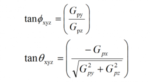
6.7 计算
偏移值和增益系数使用ADI公司应用笔记中所述的以下公式计算(第8页:公式17和18)。
在DEFINED VARIABLES代码部分中,我们将为偏移和增益放置新的计算值。
/************** DEFINED VARIABLES **************/
/*                                             */
#define offsetX     0    // OFFSET values
#define offsetY     0
#define offsetZ     0

#define gainX       1     // GAIN factors
#define gainY       1
#define gainZ       1
万岁!现在,您将能够获取X,Y和Z的调整值。
注意:您必须取消注释以下代码的一部分才能看到新的校准值:
// UNCOMMENT SECTION TO VIEW NEW VALUES
accX = (x - offsetX)/gainX;         // Calculating New Values for X, Y and Z
accY = (y - offsetY)/gainY;
accZ = (z - offsetZ)/gainZ;

Serial.print("New Calibrated Values: ");
Serial.print(accX);
Serial.print("  ");
Serial.print(accY);
Serial.print("  ");
Serial.print(accZ);
Serial.println();
现在您的串行监视器输出将被校准,看起来更像这样…

资源和进一步发展
SparkFun三重访问加速度计ADXL345和ADXL345 Arduino库都是开源的,因此有大量资源,包括:
SparkFun ADXL345 GitHub存储库
SparkFun ADXL345鹰文件
SparkFun ADXL345原理图
SparkFun ADXL345 Arduino Library GitHub存储库
有关ADXL345的更多信息,请参考数据表。
ADXL345加速度计项目启示
需要为下一个项目提供一些灵感?查看一些相关的教程。