7 working modes of ARM920T
(1) usr: normal mode
(2) sys: system
(3) Abnormal mode
- und: undefined mode
- svc: admin mode
- abt: abort mode:
- instruction prefetch
- data access
- irq: interrupt mode
- fiq: fast interrupt mode
2 states
(1) ARM instruction set
Each instruction occupies 4 bytes
(2) thumb instruction set
Each instruction occupies 2 bytes
For example, after the instructions mov r0 and r1 are compiled with different instruction sets, the space occupied by each instruction is different.
- ARM: 4byte machine code
- THUMB: 2byte machine code
register
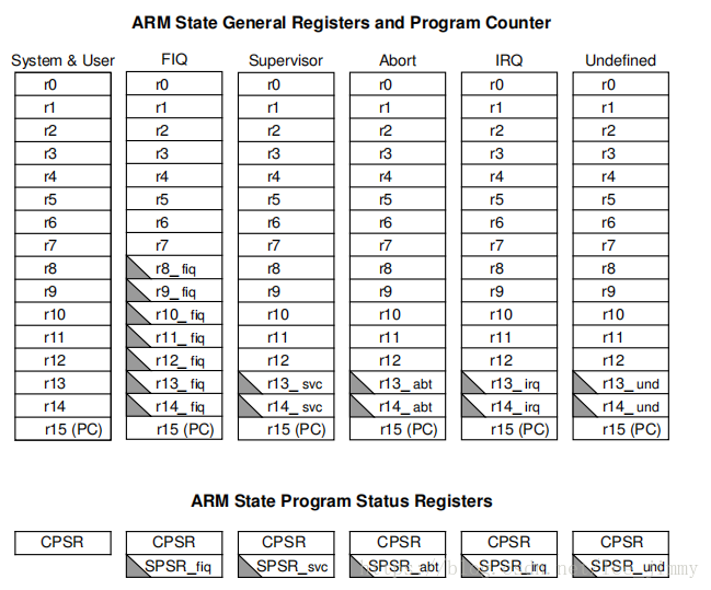
(1) We can see that some of the registers in abnormal conditions have gray triangles, indicating that in these abnormal modes, these registers are used for other purposes
Among them, r13 is the sp register we often say; r14 is the lr register, which saves the address that was put back.
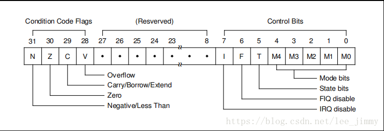
(2) The following is the meaning of each bit of the current status register (CPSR)
(3) There is also a SPSR in abnormal mode, which is used to save the value of CPSR in user mode
Simple exception handling flow description on the ARM manual
Action on Entering an Exception(进入异常模式的几个动作)While handling an exception, the ARM920T does following activities:
1. Preserves the address of the next instruction in the appropriate Link Register(LR_异常 = 下一个PC+4或者+8) . If the exception has been
entered from ARM state, then the address of the next instruction is copied into the Link Register (that is,
current PC + 4 or PC + 8 depending on the exception. See Table 2-2 on for details). If the exception has been
entered from THUMB state, then the value written into the Link Register is the current PC offset by a value
such that the program resumes from the correct place on return from the exception. This means that the
exception handler need not determine which state the exception was entered from. For example, in the case of
SWI, MOVS PC, R14_svc will always return to the next instruction regardless of whether the SWI was
executed in ARM or THUMB state.
2. Copies the CPSR into the appropriate SPSR
3. Forces the CPSR mode bits to a value which depends on the exception
4. Forces the PC to fetch the next instruction from the relevant exception vector
It may also set the interrupt disable flags to prevent otherwise unmanageable nestings of exceptions.
If the processor is in THUMB state when an exception occurs, it will automatically switch into ARM state when the
PC is loaded with the exception vector address.
On completion, the exception handler:
1. Moves the Link Register, minus an offset where appropriate, to the PC. (The offset will vary depending on the
type of exception.)
2. Copies the SPSR back to the CPSR
3. Clears the interrupt disable flags, if they were set on entry