简述
PPI扫描,即按一个仰角进行水平面上的扫描,得到二维图像的方式。它的特点是来自不同距离的回波是离地面不同的高度,扫描得到的数据在空间类似一个倒立圆锥的曲面表面。
Qt可以用OpenGL绘制复杂的图像,但为了简单和移植性,这里介绍的是用Qt自己的绘图工具QPainter绘制PPI二维图像。
实现描述
本例中使用两个类进行绘制,一个是绘制颜色标尺的paintTable类,另一个是绘制PPI扫描图主体的paintWindow类。
paintWindow类的思路就是重写paintEvent()、resizeEvent()、timerEvent()函数。每隔一段时间检查原始数据是否更新;如果数据刷新,通过repaint()函数调用paintEvent()进行重绘;当窗体大小变化时,调用resizeEvent()函数进行重绘;绘制图像的思路是绘制一个个去心的扇型片元,根据原始数据查阅调色盘,把片元绘制成不同的颜色。本例中一个方向上由300个片元组成。
paintTable类即通过几个颜色控制点,绘制一个渐变的色条。通过插值可以算得强度范围内的任意强度的RGB值。
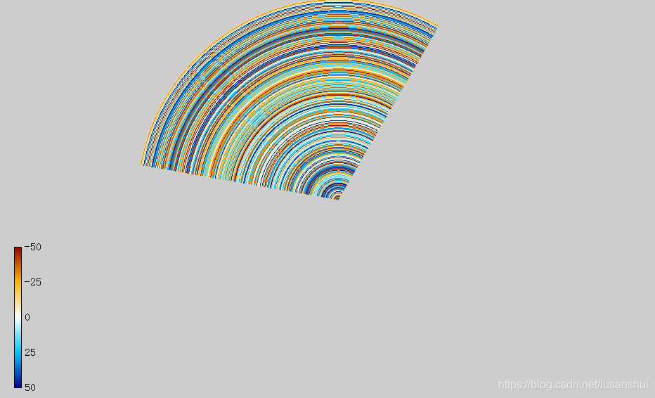
下图即使用同一组模拟数据的扫描显示图:
代码之路
paintTable类
这里ppi数据强度的范围是-50到50,使用5个控制点。
//paintTable.h
#include <QWidget>
#include <QPainter>
#include <QFont>

class paintTable : public QWidget
{
	Q_OBJECT
public:
	explicit paintTable(QWidget *parent = 0);
protected:
	void paintEvent(QPaintEvent *);
};

//paintTable.cpp
paintTable::paintTable(QWidget *parent) : QWidget(parent)
{
}
void paintTable::paintEvent(QPaintEvent *)
{
	QPainter painter(this);
	int h = height() - 200 -20;
	int w = 20;
	QRectF rect(w, h, 10, 200);
	QLinearGradient linearGradient(w, h, w + 10, h + 200);
	linearGradient.setColorAt(0, QColor(154, 0, 0));
	linearGradient.setColorAt(0.25, QColor(255, 180, 0));
	linearGradient.setColorAt(0.5, QColor(250, 255, 255));
	linearGradient.setColorAt(0.75, QColor(0, 199, 255));
	linearGradient.setColorAt(1, QColor(0, 0, 155));
	painter.setBrush(linearGradient);
	painter.drawRect(rect);

	int det = 200/4;
	painter.drawText(w + 10 + 5, h + 5, "-50");
	painter.drawText(w + 10 + 5, h + det + 5, "-25");
	painter.drawText(w + 10 + 5, h + 2*det + 5, "0");
	painter.drawText(w + 10 + 5, h + 3*det + 5, "25");
	painter.drawText(w + 10 + 5, h + 4*det + 5, "50");
}
paintWindow类
每收到一组新数据,先生成一组path和color,再绘制到image上,再直接把image替换,提高绘图效率。
//paintWindow.h
#include <QWidget>
#include <QPainter>
#include <QList>
#include <QImage>

class painterWindow : public QWidget
{
	Q_OBJECT
public:
	explicit paintWindow(QWidget *parent = 0);
	//绘制颜色表
	void drawColortable(QPainter* pp);
public slots:
	//数据更新,绘制image上
	void gradientArc(float startAngle, float angleLength);
	//参数2-6:半径 开始角度 扫取角度 圆环高度 填充色
	void gradientArc(QPainter *painter, float radius, float startAngle, float angleLength, float arcHeight, QRgb color);
protected:
	void paintEvent(QPaintEvent *);
	void timerEvent(QTimerEvent *);
	void resizeEvent(QResizeEvent *);
private:
	//绘图参数
	int winds[300];		//数值
	int m_maxWind;		//极值,默认为50
	unsigned int* m_mycolorTable;	//颜色表
	unsigned int m_colorTable[5];	//颜色表种子
	int m_numIndex[5];		//种子对应数值
	QList<QPainterPath> m_path;		//扇区/次
	QList<QRgb>	windsColor;		//颜色/次
	int m_readyDraw;		//0-not 1-ready
	QImage *image1;
	int m_colorDrawFlag;	//0-not 1-ready

	float m_width;
	float m_height;
	float m_radius;		//height()/2.0
	float m_arcHeight;	//radius/300.0
};

//paintWindow.cpp
paintWindow::paintWindow(QWidget *parent) : QWidget(parent)
{
	// Colortable
    m_colorTable[0] = 0xff9a0000;
    m_colorTable[1] = 0xffffb400;
    m_colorTable[2] = 0xffffffff;
    m_colorTable[3] = 0xff00c7ff;
    m_colorTable[4] = 0xff00009b;
    m_numIndex[0] = 0;
    m_numIndex[1] = 25;
    m_numIndex[2] = 50;
    m_numIndex[3] = 75;
    m_numIndex[4] = 100;
    // 随机生成数值(实际使用需替换真实数据)
    qsrand(0);
    for (int i = 0; i < 300; ++i)
    {
        winds[i] = qrand()%100-50;
    }
    //依据风速生成颜色
    m_maxWind = 50;
    m_mycolorTable = new unsigned int[m_maxWind*2];
    int r,g,b,sr,sg,sb,er,eg,eb,si,ei;
    float idr,idg,idb;
    for (int i = 0; i < 4; ++i)
    {
        sr = qRed(m_colorTable[i]);
        sg = qGreen(m_colorTable[i]);
        sb = qBlue(m_colorTable[i]);
        er = qRed(m_colorTable[i + 1]);
        eg = qGreen(m_colorTable[i + 1]);
        eb = qBlue(m_colorTable[i + 1]);
        si = m_numIndex[i];
        ei = m_numIndex[i+1];
        idr = (er - sr) / static_cast<float>(ei - si);
        idg = (eg - sg) / static_cast<float>(ei - si);
        idb = (eb - sb) / static_cast<float>(ei - si);
        for (int j = si; j < ei; ++j)
        {
            r = static_cast<int>(sr + (j - si)*idr);
            g = static_cast<int>(sg + (j - si)*idg);
            b = static_cast<int>(sb + (j - si)*idb);
            *(m_mycolorTable + j) = qRgb(r, g, b);
        }
    }
    //初始化qimage
    image1 = new QImage(width(), height(), QImage::Format_RGB32);
    m_radius = height()/2.0;
    m_arcHeight = (m_radius - 0)/300.0;
    m_width = width();
    m_height = height();
	//定时检查刷新
    startTimer(500);
}
void paintWindow::drawColortable(QPainter* pp)
{
	int h = height() - 200 - 20;
	int w = 20;
	QRectF rect(w, h, 10, 200);
	QLinearGradient linearGradient(w, h, w + 10, h + 200);
	linearGradient.setColorAt(0, QColor(154, 0, 0));
	linearGradient.setColorAt(0.25, QColor(255, 180, 0));
	linearGradient.setColorAt(0.5, QColor(250, 255, 255));
	linearGradient.setColorAt(0.75, QColor(0, 199, 255));
	linearGradient.setColorAt(1, QColor(0, 0, 155));
	pp->begin(image1);
	pp->setBrush(linearGradient);
	pp->drawRect(rect);

	int det = 200/4;
	pp->drawText(w + 10 + 5, h + 5, "-50");
	pp->drawText(w + 10 + 5, h + det + 5, "-25");
    pp->drawText(w + 10 + 5, h + 2*det + 5, "0");
    pp->drawText(w + 10 + 5, h + 3*det + 5, "25");
    pp->drawText(w + 10 + 5, h + 4*det + 5, "50");
    pp->end();
}
void paintWindow::gradientArc(float startAngle, float angleLength)
{
	m_path.clear();
	windsColor.clear();
	QRgb subRgb;
	float tmpRadius;
	for (int i = 0; i < 300; ++i)
	{
		QPainterPath subPath1, subPath2;
		tmpRadius = m_radius - i*m_arcHeight;
        QRectF rect(-tmpRadius, -tmpRadius, tmpRadius*2.0, tmpRadius*2.0);
        subPath1.arcTo(rect, startAngle, angleLength);
        subPath2.addEllipse(rect.adjusted(m_arcHeight,m_arcHeight, -m_arcHeight, -m_arcHeight));
        subPath1 -= subPath2;
        m_path.append(subPath1);

        subRgb = *(m_mycolorTable + (winds[i]+ m_maxWind));
        windsColor.append(subRgb);
	}
	QPainter dd;
	if (m_colorDrawFlag)
	{
		drawColortable(&dd);
		m_colorDrawFlag = 0;
	}
	dd.begin(image1);
	dd.translate(m_width/2.0, m_height/2.0);
	dd.setPen(Qt::NoPen);
	dd.setBrush(QColor(windsColor[0]));
	dd.drawPath(m_path[0]);
	for (int i = 0; i < 300; ++i)
	{
		dd.setBrush(QColor(windsColor[i]));
		dd.drawPath(m_path[i]);
	}
	dd.end();
}
void paintWindow::gradientArc(QPainter *painter, float radius, float startAngle, float angleLength, float arcHeight, QRgb color)
{
	painter->setBrush(QColor(color));
	QRectF rect(-radius, -radius, radius*2.0, radius*2.0);
	QPainterPath path;
	path.arcTo(rect, startAngle, angleLength);
	QPainterPath subPath;
	subPath.addEllipse(rect.adjusted(arcHeight, arcHeight, -arcHeight, -arcHeight));
	path -= subPath;
	painter->drawPath(path);
}
void paintWindow::paintEvent(QPaintEvent *)
{
	QPainter painter(this);
	painter.setRenderHint(QPainter::Antialiasing, true);
	painter.drawImage(QRectF(0, 0, m_width, m_height), *image1);
}
void paintWindow::timerEvent(QTimerEvent *)
{
	static int times = 1;
	time += 1;
	float d1 = times*10;
	float d2 = 10;
	gradientArc(d1, d2);
	repaint();
}
void paintWindow::resizeEvent(QResizeEvent *)
{
	if (image1 != NULL)
	{
		delete image1;
	}
	image1 = new QImage(width(), height(), QImage::Format_RGB32);
	m_radius = height()/2.0;
	m_arcHeight = (m_radius - 0)/300.0;
	m_width = width();
	m_height = height();
	m_colorDrawFlag = 1;
}
使用时,只需要在一个widget中生成对象实例,加入布局即可,如下所示:
m_paintWindow = new paintWindow();
m_paintTable = new paintTable();
QGridLayout *scrollLayout = new QGridLayout();
ui->scrollArea->setLayout(scrollLayout);
scrollLayout->addWidget(m_paintTable, 0, 0, 1, 1);
scrollLayout->addWidget(m_paintWindow, 0, 0, 1, 1);
写在最后
虽然实现了PPI扫描动态显示,但还有一些需要后期调整的地方:
1、数据是rand()函数生成,需要添加接收数据接口;
2、绘图效率在0.3s左右,相对于OpenGL绘图效率很慢,可能还有优化的空间;
3、后面已经把paintTable的绘制合并到了paintWindows类中,已经无需实现paintTable类了。
