大家好,接下来将为大家介绍OpenGL ES 3. 纹理映射。
1、纹理映射原理
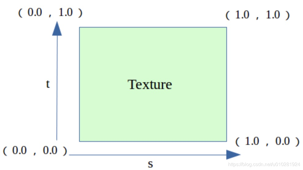
启用纹理映射功能后,如果想把纹理应用到相应的几何图元,就必须告知渲染系统如何进行纹理的映射。告知的方式就是为图元中的顶点指定恰当的纹理坐标,纹理坐标用浮点数来表 示,范围一般从 0.0 到 1.0 。
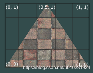
如下图所示,要想将正三角形纹理正确的显示出来,需要告诉OpenGL,三角形中每个顶点的纹理坐标是多少(左下角顶点(0,0);右下角顶点(1,0);上中顶点(0.5,1))。
2、一个简单的例子
本案例基于前面小节内容所介绍的GLSurfaceView来实现的。
如下MySurfaceView类,用于创建OpenGL ES 相关的渲染器Render,创建纹理对象,指定OpenGL的投影方式等。
import android.graphics.BitmapFactory;

class MySurfaceView extends GLSurfaceView
{
    private SceneRenderer mRenderer;//场景渲染器

    int textureId;//系统分配的纹理id

	public MySurfaceView(Context context) {
        super(context);
        this.setEGLContextClientVersion(3);	//设置使用OPENGL ES3.0
        mRenderer = new SceneRenderer();	//创建场景渲染器
        setRenderer(mRenderer);				//设置渲染器
        setRenderMode(GLSurfaceView.RENDERMODE_CONTINUOUSLY);//设置渲染模式为主动渲染
    }


	private class SceneRenderer implements GLSurfaceView.Renderer
    {
    	Triangle texRect;//纹理三角形对象引用

        public void onDrawFrame(GL10 gl)
        {
        	//清除深度缓冲与颜色缓冲
            GLES30.glClear( GLES30.GL_DEPTH_BUFFER_BIT | GLES30.GL_COLOR_BUFFER_BIT);
            //绘制纹理三角形
            texRect.drawSelf(textureId);
        }

        public void onSurfaceChanged(GL10 gl, int width, int height) {
            //设置视窗大小及位置
        	GLES30.glViewport(0, 0, width, height);
        	//计算GLSurfaceView的宽高比
            float ratio = (float) width / height;
            //调用此方法计算产生透视投影矩阵
            MatrixState.setProjectFrustum(-ratio, ratio, -1, 1, 1, 10);
            //调用此方法产生摄像机9参数位置矩阵
            MatrixState.setCamera(0,0,3,0f,0f,0f,0f,1.0f,0.0f);
        }

        public void onSurfaceCreated(GL10 gl, EGLConfig config) {
            //设置屏幕背景色RGBA
            GLES30.glClearColor(0.5f,0.5f,0.5f, 1.0f);
            //创建三角形对对象
            texRect=new Triangle(MySurfaceView.this);
            //打开深度检测
            GLES30.glEnable(GLES30.GL_DEPTH_TEST);
            //初始化纹理
            initTexture();
            //关闭背面剪裁
            GLES30.glDisable(GLES30.GL_CULL_FACE);
        }
    }

	public void initTexture()//textureId
	{
		//生成纹理ID
		int[] textures = new int[1];
		GLES30.glGenTextures
		(
				1,          //产生的纹理id的数量
				textures,   //纹理id的数组
				0           //偏移量
		);
		textureId=textures[0];
		GLES30.glBindTexture(GLES30.GL_TEXTURE_2D, textureId);
		GLES30.glTexParameterf(GLES30.GL_TEXTURE_2D, GLES30.GL_TEXTURE_MIN_FILTER,GLES30.GL_NEAREST);
		GLES30.glTexParameterf(GLES30.GL_TEXTURE_2D,GLES30.GL_TEXTURE_MAG_FILTER,GLES30.GL_LINEAR);
		GLES30.glTexParameterf(GLES30.GL_TEXTURE_2D, GLES30.GL_TEXTURE_WRAP_S,GLES30.GL_CLAMP_TO_EDGE);
		GLES30.glTexParameterf(GLES30.GL_TEXTURE_2D, GLES30.GL_TEXTURE_WRAP_T,GLES30.GL_CLAMP_TO_EDGE);
        //通过输入流加载图片===============begin===================
        InputStream is = this.getResources().openRawResource(R.drawable.wall);
        Bitmap bitmapTmp;
        try
        {
        	bitmapTmp = BitmapFactory.decodeStream(is);
        }
        finally
        {
            try
            {
                is.close();
            }
            catch(IOException e)
            {
                e.printStackTrace();
            }
        }
        //通过输入流加载图片===============end=====================

        //实际加载纹理进显存
        GLUtils.texImage2D
        (
        		GLES30.GL_TEXTURE_2D, //纹理类型
        		0, 					  //纹理的层次,0表示基本图像层,可以理解为直接贴图
        		bitmapTmp, 			  //纹理图像
        		0					  //纹理边框尺寸
        );
        bitmapTmp.recycle(); 		  //纹理加载成功后释放内存中的纹理图
	}
}
其中,initTexture()方法是非常常用的,用于创建OpenGL ES 纹理的方法。
如下MatrixState是非常好用的一个矩阵操作类,封装了摄像机设置,投影方式设置,物体变换矩阵等接口。
import android.opengl.Matrix;

//存储系统矩阵状态的类
public class MatrixState
{
	private static float[] mProjMatrix = new float[16];//4x4矩阵 投影用
    private static float[] mVMatrix = new float[16];//摄像机位置朝向9参数矩阵
    private static float[] mMVPMatrix;//最后起作用的总变换矩阵
    static float[] mMMatrix=new float[16] ;//具体物体的移动旋转矩阵

    public static void setInitStack()//获取不变换初始矩阵
    {
    	Matrix.setRotateM(mMMatrix, 0, 0, 1, 0, 0);
    }

    public static void translate(float x,float y,float z)//设置沿xyz轴移动
    {
    	Matrix.translateM(mMMatrix, 0, x, y, z);
    }

    public static void rotate(float angle,float x,float y,float z)//设置绕xyz轴转动
    {
    	Matrix.rotateM(mMMatrix,0,angle,x,y,z);
    }


    //设置摄像机
    public static void setCamera
    (
    		float cx,	//摄像机位置x
    		float cy,   //摄像机位置y
    		float cz,   //摄像机位置z
    		float tx,   //摄像机目标点x
    		float ty,   //摄像机目标点y
    		float tz,   //摄像机目标点z
    		float upx,  //摄像机UP向量X分量
    		float upy,  //摄像机UP向量Y分量
    		float upz   //摄像机UP向量Z分量
    )
    {
    	Matrix.setLookAtM
        (
        		mVMatrix,
        		0,
        		cx,
        		cy,
        		cz,
        		tx,
        		ty,
        		tz,
        		upx,
        		upy,
        		upz
        );
    }

    //设置透视投影参数
    public static void setProjectFrustum
    (
    	float left,		//near面的left
    	float right,    //near面的right
    	float bottom,   //near面的bottom
    	float top,      //near面的top
    	float near,		//near面距离
    	float far       //far面距离
    )
    {
    	Matrix.frustumM(mProjMatrix, 0, left, right, bottom, top, near, far);
    }

    //获取具体物体的总变换矩阵
    public static float[] getFinalMatrix()
    {
    	mMVPMatrix=new float[16];
    	Matrix.multiplyMM(mMVPMatrix, 0, mVMatrix, 0, mMMatrix, 0);
        Matrix.multiplyMM(mMVPMatrix, 0, mProjMatrix, 0, mMVPMatrix, 0);
        return mMVPMatrix;
    }
}
如下Triangle是三角形的操作封装。
import java.nio.ByteBuffer;
import java.nio.ByteOrder;
import java.nio.FloatBuffer;
import android.opengl.GLES30;

//纹理三角形
public class Triangle
{
	int mProgram;//自定义渲染管线程序id
    int muMVPMatrixHandle;//总变换矩阵引用
    int maPositionHandle; //顶点位置属性引用
    int maTexCoorHandle; //顶点纹理坐标属性引用
    String mVertexShader;//顶点着色器代码脚本
    String mFragmentShader;//片元着色器代码脚本

	FloatBuffer   mVertexBuffer;//顶点坐标数据缓冲
	FloatBuffer   mTexCoorBuffer;//顶点纹理坐标数据缓冲
    int vCount=0;
    float xAngle=0;//绕x轴旋转的角度
    float yAngle=0;//绕y轴旋转的角度
    float zAngle=0;//绕z轴旋转的角度

    public Triangle(MySurfaceView mv)
    {
    	//初始化顶点数据的方法
    	initVertexData();
    	//初始化着色器的方法
    	initShader(mv);
    }

    //初始化顶点数据的方法
    public void initVertexData()
    {
    	//顶点坐标数据的初始化================begin============================
        vCount=3;

        float vertices[]=new float[]
        {
        	0,  1,  0,
        	-1, -1, 0,
        	1,  -1, 0
        };

        //创建顶点坐标数据缓冲
        //vertices.length*4是因为一个整数四个字节
        ByteBuffer vbb = ByteBuffer.allocateDirect(vertices.length*4);
        vbb.order(ByteOrder.nativeOrder());//设置字节顺序
        mVertexBuffer = vbb.asFloatBuffer();//转换为Float型缓冲
        mVertexBuffer.put(vertices);//向缓冲区中放入顶点坐标数据
        mVertexBuffer.position(0);//设置缓冲区起始位置
        //特别提示:由于不同平台字节顺序不同数据单元不是字节的一定要经过ByteBuffer
        //转换,关键是要通过ByteOrder设置nativeOrder(),否则有可能会出问题
        //顶点坐标数据的初始化================end============================

        //顶点纹理坐标数据的初始化================begin============================
        float texCoor[]=new float[]//顶点颜色值数组,每个顶点4个色彩值RGBA
        {
        	0.5f,0,
        	0,1,
        	1,1
        };
        //创建顶点纹理坐标数据缓冲
        ByteBuffer cbb = ByteBuffer.allocateDirect(texCoor.length*4);
        cbb.order(ByteOrder.nativeOrder());//设置字节顺序
        mTexCoorBuffer = cbb.asFloatBuffer();//转换为Float型缓冲
        mTexCoorBuffer.put(texCoor);//向缓冲区中放入顶点纹理数据
        mTexCoorBuffer.position(0);//设置缓冲区起始位置
        //特别提示:由于不同平台字节顺序不同数据单元不是字节的一定要经过ByteBuffer
        //转换,关键是要通过ByteOrder设置nativeOrder(),否则有可能会出问题
        //顶点纹理坐标数据的初始化================end============================

    }

    //初始化着色器
    public void initShader(MySurfaceView mv)
    {
    	//加载顶点着色器的脚本内容
        mVertexShader=ShaderUtil.loadFromAssetsFile("vertex.sh", mv.getResources());
        //加载片元着色器的脚本内容
        mFragmentShader=ShaderUtil.loadFromAssetsFile("frag.sh", mv.getResources());
        //基于顶点着色器与片元着色器创建程序
        mProgram = createProgram(mVertexShader, mFragmentShader);
        //获取程序中顶点位置属性引用
        maPositionHandle = GLES30.glGetAttribLocation(mProgram, "aPosition");
        //获取程序中顶点纹理坐标属性引用
        maTexCoorHandle= GLES30.glGetAttribLocation(mProgram, "aTexCoor");
        //获取程序中总变换矩阵引用
        muMVPMatrixHandle = GLES30.glGetUniformLocation(mProgram, "uMVPMatrix");
    }

    public void drawSelf(int texId)
    {
    	 //指定使用某套shader程序
    	 GLES30.glUseProgram(mProgram);

    	 MatrixState.setInitStack();

         //设置沿Z轴正向位移1
         MatrixState.translate(0, 0, 1);

         //设置绕y轴旋转
         MatrixState.rotate(yAngle, 0, 1, 0);
         //设置绕z轴旋转
         MatrixState.rotate(zAngle, 0, 0, 1);
         //设置绕x轴旋转
         MatrixState.rotate(xAngle, 1, 0, 0);
         //将最终变换矩阵传入渲染管线
         GLES30.glUniformMatrix4fv(muMVPMatrixHandle, 1, false, MatrixState.getFinalMatrix(), 0);
         //将顶点位置数据传送进渲染管线
         GLES30.glVertexAttribPointer
         (
         		maPositionHandle,
         		3,
         		GLES30.GL_FLOAT,
         		false,
                3*4,
                mVertexBuffer
         );
         //将顶点纹理坐标数据传送进渲染管线
         GLES30.glVertexAttribPointer
         (
        		maTexCoorHandle,
         		2,
         		GLES30.GL_FLOAT,
         		false,
                2*4,
                mTexCoorBuffer
         );
         //允许顶点位置数据数组
         GLES30.glEnableVertexAttribArray(maPositionHandle);//启用顶点位置数据
         GLES30.glEnableVertexAttribArray(maTexCoorHandle);//启用顶点纹理坐标数据
         //绑定纹理
         GLES30.glActiveTexture(GLES30.GL_TEXTURE0);//设置使用的纹理编号
         GLES30.glBindTexture(GLES30.GL_TEXTURE_2D, texId);//绑定指定的纹理id
         //以三角形的方式填充
         GLES30.glDrawArrays(GLES30.GL_TRIANGLES, 0, vCount);
    }
}
值得注意的是:三角形的纹理坐标,其Y坐标相对于开篇图示,做了Y方向的翻转。
float vertices[]=new float[]
{
0, 1, 0,
-1, -1, 0,
1, -1, 0
};
float texCoor[]=new float[]
{
0.5f, 0,
0, 1,
1, 1
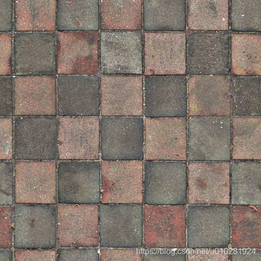
}; 3、原图与渲染结果
待渲染图片如下:
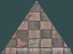
渲染结果如下:
最后,欢迎大家一起交流学习:微信:liaosy666 ; QQ:2209115372 。
