需求分析:
由于接入备份的需要,用户部署了冗余链路。冗余备份链路的存在导致出现环网,可能会引起广播风暴和MAC地址表项被破坏。
用户希望在有冗余备份链路的同时消除网络中的环路,在-条上行链路断开时,流量能切换到另外一条 上行链路转发,还能合理利用网络带宽。
拓扑图:
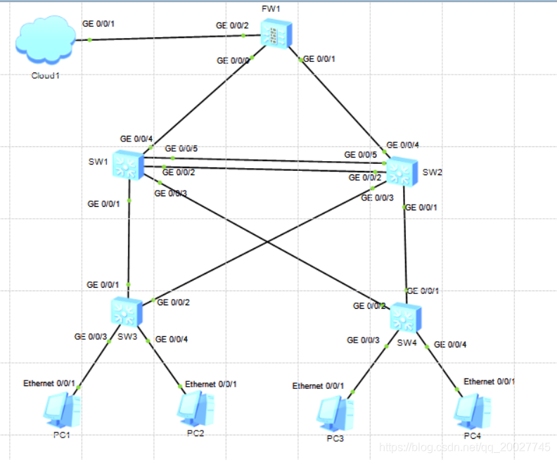
拓扑描述
MSTP可阻塞二层网络中的冗余链路 ,将网络修剪成树状,达到消除环路的目的。同时在SW1和SW2上配置VRRP , PC1以SW1为默认网关接入Internet , SW2作为备份网关; PC3以SW2为默认网关接入Internet , SW1作为备份网关,以实现可靠性及流量的负载分担。
SW1交换机:配置vlan2地址为172.16.2.253/24 ,配置vlan7地址为172.16.7.253/24。
SW2交换机:配置vlan2地址为172.16.2.252/24 ,配置vlan7地址为172.16.7.252/24。
VRRP配置vlan2用户网络虚拟网关为172.16.2.254 ,配置vlan7用户网络虚拟网关为172.16.7.254。
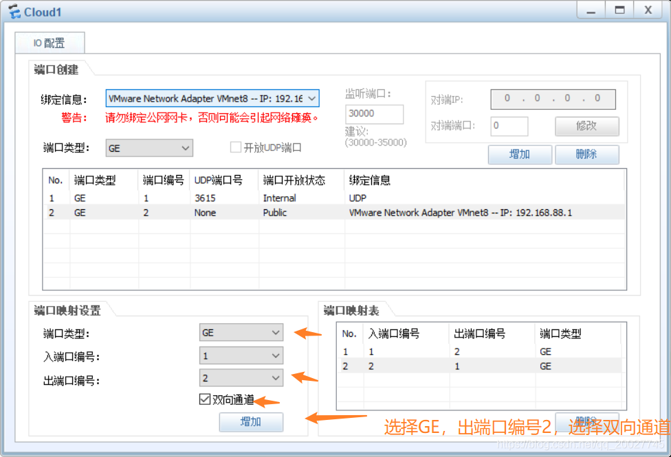
1.Cloud1配置:
(1)双击Cloud1设备,进入设置界面。
注:添加端口完成后才能与其他设备连接网线!
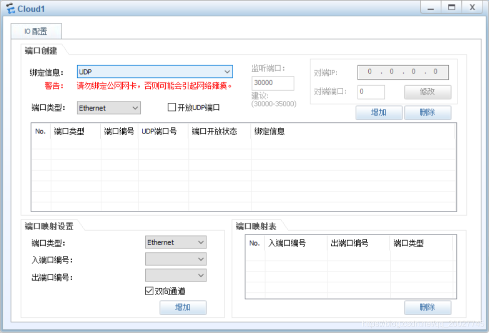
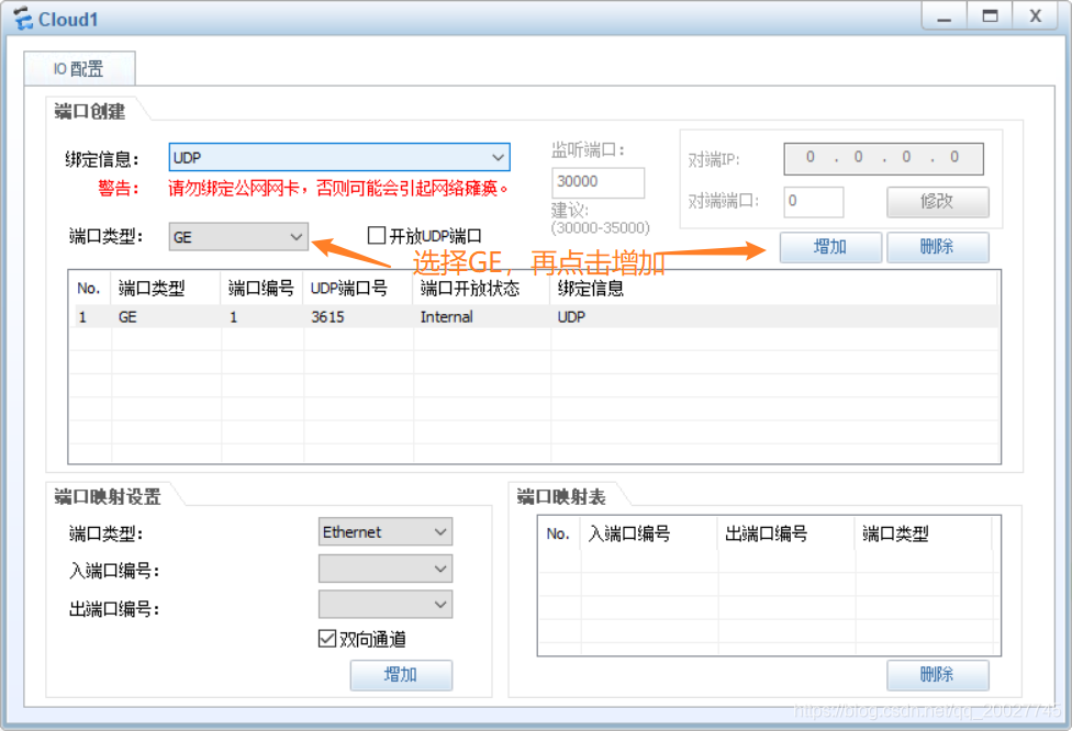
(2)添加UDP端口。
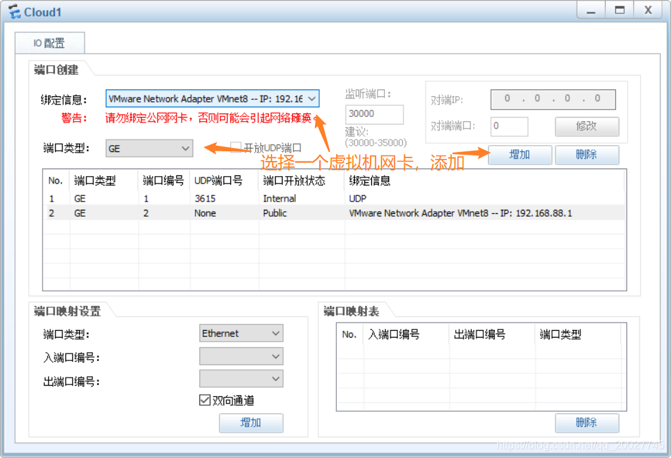
(3)添加物理机虚拟机网卡。
(4)添加端口映射。
2.FW1防火墙配置:
<SRG>sys
[SRG]sysname FW1
[FW1]interface GigabitEthernet O/0/0
[FW1-GigabitEthernet0/0/D]ip address 192.168.2.1 24
[FW1-GigabitEthernet0/0/0]quit
[FW1]
[FW1]interface GigabitEthernet 0/0/1
[FW1-GigabitEthernet0/0/1]ip address 192.168.3.1 24
[FW1-GigabitEthernet0/0/1]quit
[FW1]
[FW1]interface GigabitEthernet 0/0/2
[FW1-GigabitEthernet0/0/2]ip address 192.168.88.9 24
[FW1]firewall zone trust
[FW1-zone-trust]add interface GigabitEthernet O/0/0
[FW1-zone-trust]add interface GigabitEthernet 0/0/1
[FW1-zone-trust]quit
[FW1]
[FW1]firewall zone untrust
[FW1-zone-untrust]add interface GigabitEthernet 0/0/2
[FW1-zone-untrust]quit
[FW1]
[FW1]policy interzonetrust untrust outbound
[FW1-policy-interzone-trust-untrust-outbound]policy 0
[FW1-policy-interzone-trust-untrust-outbound-0]action permit
[FW1-policy-interzone-trust-untrust-outbound-0]policy source 172.16.2.0 0.0.0.255 i
[FW1-policy-interzone-trust-untrust-outbound-0]policy source 172.16.7.0 0.0.0.255
[FW1-policy-interzone-trust-untrust-outbound-0]quit
[FW1-policy-interzone-trust-untrust-outbound]quit
[FW1]
[FW1]nat-policy interzone trust untrust outbound
[FW1-nat policy-interzone-trust-untrust-outbound]policy 1
[FW1-nat-policy-interzone-trust-untrust-outbound-1]action source-nat
[FW1-nat-policy-interzone-trust-untrust-outbound-1]policy source 172.16.2.0.0.0.0.255
[FW1-nat-policy-interzone-trust-untrust-outbound-1]policy source 172.16.7.0 0.0.0.255
[FW1-nat-policy-interzone-trust-untrust-outbound-1]easy-ip GigabitEthernet 0/0/2
[FW1-nat-policy-interzone-trust-untrust-outbound-1]quit
[FW1-nat-policy-interzone-trust-untrust-outbound]quit
[FW1]ip route-static 0.0.0.0 0 192.168.88.1
[FW1]ospf 1
[FW1-ospf-1]default-route- advertise always cost 200 type 1
[FW1-ospf-1]area 0
[FW1-ospf-1-area-0.0.0.0]network 192.168.2.0 0.0.0.255
[FW1-ospf-1-area-0.0.0.0]network 192.168.3.0 0.0.0.255
3.SW1交换机配置:
<Huawei>system-view
[Huawei]sysname SW1
[SW1]vlan batch 2 7 102 103
[SW1]interface Vlanif 102
[SW1-Vlanif102]ip address 192.168.2.2 24
[SW1-Vlanif102]quit
[SW1]
[SW1]interface GigabitEthernet 0/0/4
[SW1-GigabitEthernet0/0/4]port link-type access
[SW1-GigabitEthernet0/0/4]port default vlan 102
[SW1-GigabitEthernet0/0/4]quit
[SW1]
[SW1]interface GigabitEthernet 0/0/1
[SW1-GigabitEthernet0/0/1]port link-type trunk
[SW1-GigabitEthernet0/0/1]port trunk allow-pass vlan 2 7 102 103
[SW1-GigabitEthernet0/0/1]quit
[SW1]
[SW1]interface GigabitEthernet 0/0/3
[SW1-GigabitEthernet0/0/3]port link-type trunk
[SW1-GigabitEthernet0/0/3]port trunk allow-pass vlan 2 7 102 103
[SW1-GigabitEthernet0/0/3]quit
[SW1]
[SW1]interface Eth-Trunk 0 		//创建并进入链路聚合组0中
[SW1-Eth-Trunk0]port link-type trunk
[SW1-Eth-Trunk0]port trunk allow-pass vlan 2 7 102 to 103
[SW1-Eth-Trunk0]trunkport GigabitEthernet 0/0/2
[SW1-Eth-Trunk0]trunkport GigabitEthernet 0/0/5
[SW1-Eth-Trunk0]quit
[SW1]
[SW1]interface Vlanif 2
[SW1-Vlanif2]ip address 172.16.2.253 24
[SW1-Vlanif2]vrrp vrid 1 virtual-ip 172.16.2.254
[SW1-Vlanif2]vrrp vrid 1 priority 120
[SW1-Vlanif2]vrrp vrid 1 track interface GigabitEthernet 0/0/4 reduced 15
[SW1-Vlanif2]vrrp vrid 1 track interface Eth-Trunk 0 reduced 15
[SW1-Vlanif2]quit
[SW1]
[SW1]interface Vlanif 7
[SW1-Vlanif7]ip address 172.16.7.253 24
[SW1-Vlanif7]vrrp vrid 2 virtual-ip 172.16.7.254
[SW1-Vlanif7]quit
[SW1]
[SW1]ip route-static 0.0.0.0 0 192.168.2.1
[SW1]stp region-configuration
[SW1-mst-region]region-name RG1
[SW1-mst-region]instance 1 vlan 2
[SW1-mst-region]instance 2 vlan 7
[SW1-mst-region]active region-configuration
[SW1-mst-reaion]quit
[SW1]
[SW1]stp instance 1 root primary
[SW1]stp instance 2 root secondary
[SW1]stp pathcost-standard legacy
[SW1]stp enable
[SW1]ospf 1
[SW1-ospf-1]area 0
[SW1-ospf-1-area-0.0.0.0]network 192.168.2.0 0.0.0.255
[SW1-ospf-1-area-0.0.0.0]network 172.16.2.0 0.0.0.255
[SW1-ospf-1-area-0.0.0.0]network 172.16.7.0 0.0.0.255
4.SW2交换机配置:
<Huawei>system-view
[Huawei]sysname SW2
[SW2]interface Vlanif 103
[SW2-Vlanif102]ip address 192.168.3.2 24
[SW2-Vlanif102]quit
[SW2]
[SW2]interface GigabitEthernet 0/0/4
[SW2-GigabitEthernet0/0/4]port link-type access
[SW2-GigabitEthernet0/0/4]port default vlan 103
[SW2-GigabitEthernet0/0/4]quit
[SW2]
[SW2]interface GigabitEthernet 0/0/1
[SW2-GigabitEthernet0/0/1]port link-type trunk
[SW2-GigabitEthernet0/0/1]port trunk allow-pass vlan 2 7 102 103
[SW2-GigabitEthernet0/0/1]quit
[SW2]
[SW2]interface GigabitEthernet 0/0/3
[SW2-GigabitEthernet0/0/3]port link-type trunk
[SW2-GigabitEthernet0/0/3]port trunk allow-pass vlan 2 7 102 103
[SW2-GigabitEthernet0/0/3]quit
[SW2]
[SW2]interface Eth-Trunk 0 		//创建并进入链路聚合组0中
[SW2-Eth-Trunk0]port link-type trunk
[SW2-Eth-Trunk0]port trunk allow-pass vlan 2 7 102 to 103
[SW2-Eth-Trunk0]trunkport GigabitEthernet 0/0/2
[SW2-Eth-Trunk0]trunkport GigabitEthernet 0/0/5
[SW2-Eth-Trunk0]quit
[SW2]
[SW2]interface Vlanif 2
[SW2-Vlanif2]ip address 172.16.2.252 24
[SW2-Vlanif2]vrrp vrid 1 virtual-ip 172.16.2.254
[SW2-Vlanif2]quit
[SW2]
[SW2]interface Vlanif 7
[SW2-Vlanif7]ip address 172.16.7.252 24
[SW2-Vlanif7]vrrp vrid 2 virtual-ip 172.16.7.254
[SW2-Vlanif7]vrrp vrid 2 priority 120
[SW2-Vlanif7]vrrp vrid 2 track interface GigabitEthernet 0/0/4 reduced 15
[SW2-Vlanif7]vrrp vrid 2 track interface Eth-Trunk 0 reduced 15
[SW2-Vlanif7]quit
[SW2]
[SW2]ip route-static 0.0.0.0 0 192.168.3.1
[SW2]stp region-configuration
[SW2-mst-region]region-name RG1
[SW2-mst-region]instance 1 vlan 2
[SW2-mst-region]instance 2 vlan 7
[SW2-mst-region]active region-configuration
[SW2-mst-reaion]quit
[SW2]
[SW2]stp instance 1 root secondary
[SW2]stp instance 2 root primary
[SW2]stp pathcost-standard legacy
[SW2]stp enable
[SW2]ospf 1
[SW2-ospf-1]area 0
[SW2-ospf-1-area-0.0.0.0]network 192.168.3.0 0.0.0.255
[SW2-ospf-1-area-0.0.0.0]network 172.16.2.0 0.0.0.255
[SW1-ospf-1-area-0.0.0.0]network 172.16.7.0 0.0.0.255
5.SW3交换机配置:
<Huawei> system-view
[Huawei]sysname SW3
[SW3]vlan batch 2 7 102 103
[SW3]interface GigabitEthernet O/0/1
[SW3-GigabitEthernet0/0/1]port link-type trunk
[SW3-GigabitEthernet0/0/1]port trunk allow-pass vlan 2 7 102 103
[SW3-GigabitEthernet0/0/1]quit
[SW3]
[SW3]interface GigabitEthernet 0/0/2
[SW3-GigabitEthernet0/0/2]port link-type trunk
[SW3-GigabitEthernet0/0/2]port trunk allow-pass vlan 2 7 102 103
[SW3-GigabitEthernet0/0/2]quit
[SW3]
[SW3]interface GigabitEthernet 0/0/3
[SW3-GigabitEthernet0/0/3]port link type access
[SW3-GigabitEthernet0/0/3]port default vlan 2
[SW3-GigabitEthernetO/0/3]quit
[SW3]
[SW3]interface GigabitEthernet 0/0/4
[SW3-GigabitEthernet0/0/4]port link type access
[SW3-GigabitEthernet0/0/4]port default vlan 7
[SW3-GigabitEthernet0/0/4]quit
[SW3]
[SW3]stp region-configuration
[SW3-mst-region]region-name RG1
[SW3-mst-region]instance 1 vlan2 			//创建实例1 ,并将vlan2放入实例1中
[SW3-mst-region]instance 2 vlan 7 			//创建实例2 ,并将vlan7放入实例2中
[SW3-mst-region]active region-configuration //激活以上配置,否则配置不生效也看不到
[SW3-mst-region]quit
[SW3]stp enable
注:SW4交换机配置同SW3一样
6.查看信息
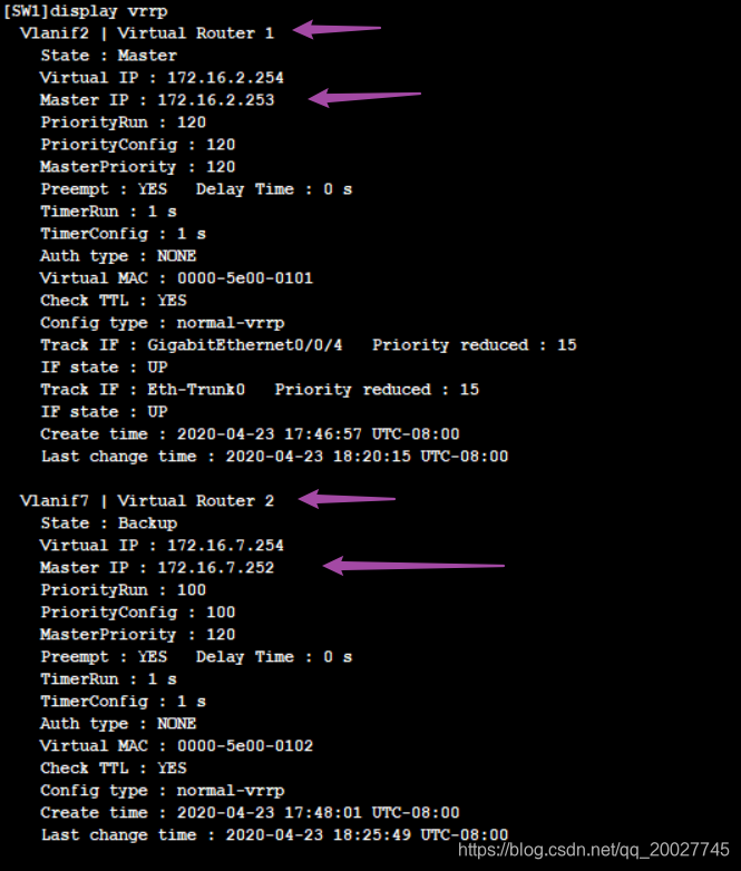
(1)查看SW1交换机的VRRP信息
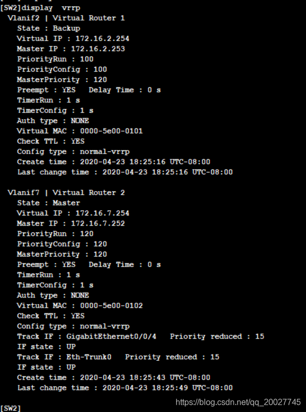
(2)查看SW2交换机的VRRP信息
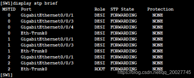
(3)查看SW1交换机STP信息
6.配置PC机:
(1)配置PC1的IP地址为172.16.2.11,网关为172.16.2.254。

(2)配置PC2的IP地址为172.16.7.11,网关为172.16.7.254。

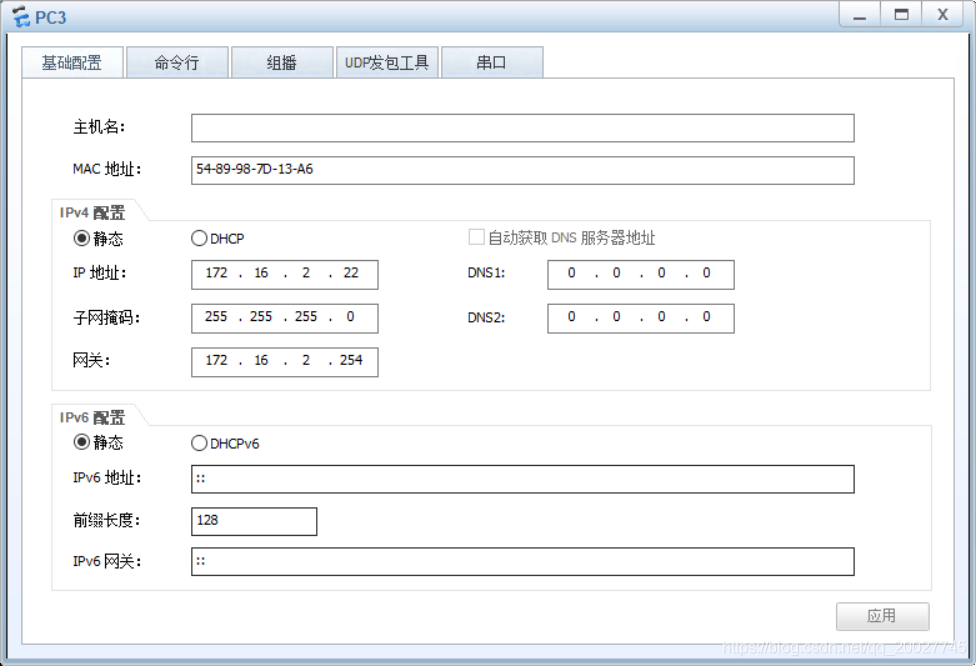
(3)配置PC3的IP地址为172.16.2.22,网关为172.16.2.254。
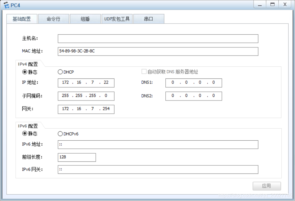
(4)配置PC4的IP地址为172.16.7.22,网关为172.16.7.254。
7.测试PC机连通性:
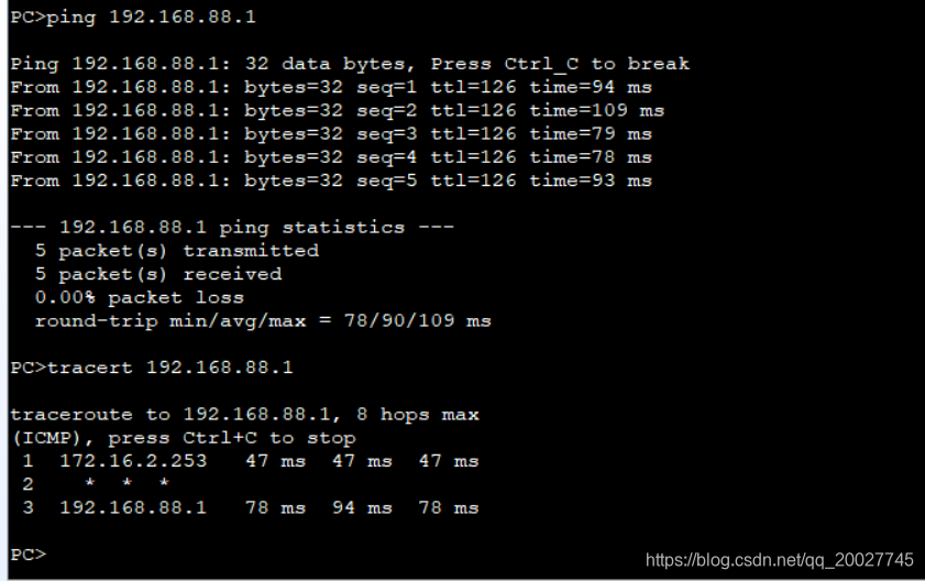
(1)PC1 Ping 外网测试
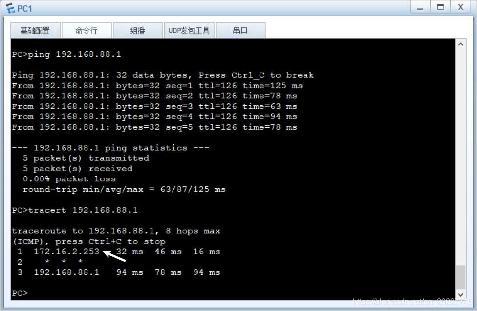
可以连通外网,经过Vlan 2到达Cloud1。
(2)PC2 Ping 外网测试
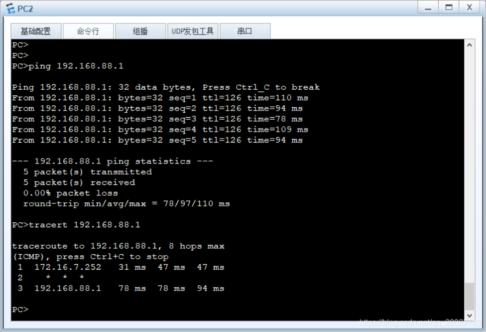
可以连通外网,经过Vlan 7到达Cloud1。
(3)PC3 Ping 外网测试
实验结果同PC1。
(4)PC4 Ping 外网测试
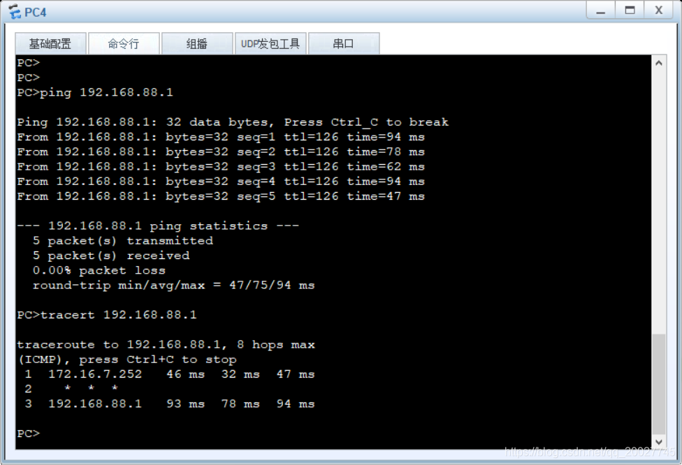
实验结果同PC2。
