通过相机标定可以获取两个相机各自的内参矩阵和畸变系数,以及两个相机各自的旋转矩阵及平移矩阵。Calibration Toolbox for Matlab 工具箱提供了相机的标定方法以及双目系统的标定及校正方法。
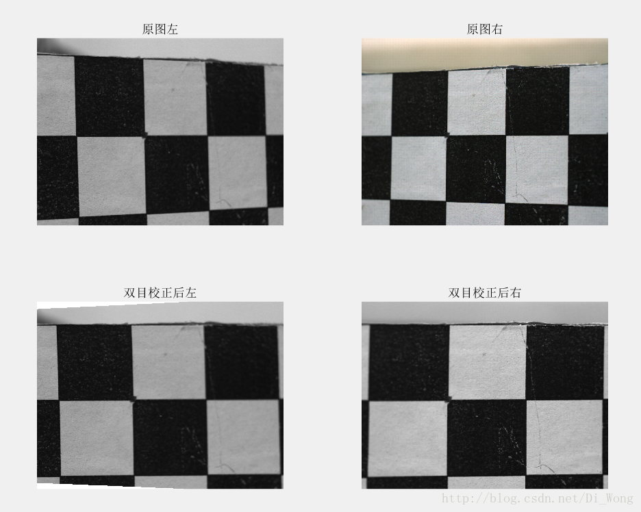
双目校正的作用就是要把消除畸变后的两幅图像严格地行对应,使得两幅图像的对极线恰好在同一水平线上,这样一幅图像上任意一点与其在另一幅图像上的对应点就必然具有相同的行号,只需在该行进行一维搜索即可匹配到对应点。
工具箱中有一项功能是校正标定图像,如图1红框所示,点击该按钮就能对标定用的棋盘图像进行双目校正,但是该工具箱并没有提供对需要进行三维重建的图像进行校正的方法,在网上的利用matlab实现双目校正的例程也比较少,于是我在这里做一个总结。
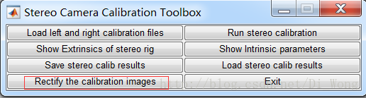
图1 Calibration Toolbox for Matlab 工具箱
一、程序来源说明
本文中所使用的程序是基于 Jean-Yves Bouguet 发布于http://www.vision.caltech.edu/bouguetj/calib_doc/index.html#examples 的 Calibration Toolbox for Matlab 工具箱中 rectify_stereo_pair.m 文件改动而来(文件所在路径D:\Program Files\MATLAB\R2015b\toolbox\TOOLBOX_calib)。
下载工具箱请点击这里。
本文旨在说明如何利用由工具箱标定出的相机内外参数进行双目校正,关于如何安装工具箱、如何进行相机标定、相机标定原理、利用极线约束进行双目校正的原理等内容,本文在这里不再赘述。
二、程序示例
本文例程所使用的相机内外参数格式形式是使用Calibration Toolbox for Matlab 工具箱经过:
1、对两个相机分别进行标定得到各自的内外参数,教程步骤参考http://www.vision.caltech.edu/bouguetj/calib_doc/htmls/example.html
2、对两个相机进行双目系统标定,教程步骤参考http://www.vision.caltech.edu/bouguetj/calib_doc/htmls/example5.html
经过这两个步骤之后,得到如图2所示的相机内外参数。具体参数描述参考http://www.vision.caltech.edu/bouguetj/calib_doc/htmls/parameters.html

图2 标定后所得内外参数及其格式
程序说明:
在程序中调用rectify_stereo_pair_selfmade.m
,调用格式为[XL,XR] = rectify_stereo_pair_selfmade(I_left,I_right),即能对图像进行双目校正。其中
I_left、
I_right为左右相机采集到的未校正图像矩阵,XL、XR为校正后图像矩阵。
注意,在使用函数时,将经过步骤1、2后得到的数据 Calib_Results_stereo.mat 与main.m 和 rectify_stereo_pair_selfmade.m 放在同一目录下。
程序 rectify_stereo_pair_selfmade.m 中使用的 rodrigues () 函数为工具箱中函数,作用是对 3x1 阶矩阵 om 进行罗德里格变换。
软件版本:MATLAB R2015b
main.m
I_left = imread('measuredleft1.bmp');
I_right = imread('measuredright1.bmp');
[XL,XR] = rectify_stereo_pair_selfmade(I_left,I_right);%对输入图像进行双目校正
imwrite(mat2gray(XL),'measuredleft1_rectify.bmp');
imwrite(mat2gray(XR),'measuredright1_rectify.bmp');
rectify_stereo_pair_selfmade.m
function [XL,XR] = rectify_stereo_pair_selfmade(I_left,I_right)

% function [XL,XR] = rectify_stereo_pair_selfmade[I_left,I_left]
% 函数功能:消除图像畸变并进行双目校正
%注意: 在该函数中两个相机的内外参数均默认为已知,其中
%       fc_right        2x1 matrix          fc_left         2x1 matrix       om     3x1 matrix
%       cc_right        2x1 matrix          cc_left         2x1 matrix       T      3x1 matrix
%       kc_right        5x1 matrix          kc_left         5x1 matrix
%       alpha_c_right   1x1 matrix          alpha_c_left    1x1 matrix
%
%       相机内外参数均默认使用Jean-Yves Bouguet制作的 Camera Calibration Toolbox for Matlab工具箱求得
%
%
% Input:
%           I_left: 左相机未校正图像矩阵
%           I_right: 右相机未校正图像矩阵
%
% Output:
%
%           XL:校正后 2xN 阶左相机图像矩阵
%           XR:校正后 2xN 阶右相机图像矩阵
%
% For Example:
%           I_left = imread('left1.bmp');
%           I_right = imread('right1.bmp');
%           [XL,XR] = rectify_stereo_pair_selfmade(I_left,I_right);
%           imwrite(mat2gray(XL),'left1_rectify.bmp');
%           imwrite(mat2gray(XR),'right1_rectify.bmp');
%
%申明:
%
%本函数改动自Jean-Yves Bouguet制作的 Camera Calibration Toolbox for Matlab工具箱中 rectify_stereo_pair.m 函数
%更多信息请访问:http://www.vision.caltech.edu/bouguetj/calib_doc/htmls/example5.html
%
%
% For more information, visit http://www.vision.caltech.edu/bouguetj/calib_doc/htmls/example5.html
% (c) Jean-Yves Bouguet - Intel Corporation - April 9th, 2003

 if ndims(I_left) == 3  %判断矩阵维数
     I_left = double(rgb2gray (I_left));
 else
      I_left = double (I_left);
 end
 if ndims(I_right) == 3
     I_right = double(rgb2gray (I_right));
 else
      I_right = double (I_right);
 end
 [ny,nx]  = size(I_left);

if ~exist('fc_right')|~exist('cc_right')|~exist('kc_right')|~exist('alpha_c_right')|~exist('fc_left')|~exist('cc_left')|~exist('kc_left')|~exist('alpha_c_left')|~exist('om')|~exist('T')

    if exist('Calib_Results_stereo.mat')~=2,
        fprintf(1,'No stereo calibration data.\n');
        return;
    else
        fprintf(1,'\nLoading the stereo calibration file Calib_Results_stereo.mat.\n');
        load Calib_Results_stereo; % Load the stereo calibration result
    end;

end;


fprintf(1,'\nCalculating the rotation to be applied to the right and left images in order to bring the epipolar lines aligned with the horizontal scan lines, and in correspondence...\n\n');

R = rodrigues(om);

% Bring the 2 cameras in the same orientation by rotating them "minimally":
r_r = rodrigues(-om/2);
r_l = r_r';
t = r_r * T;

% Rotate both cameras so as to bring the translation vector in alignment with the (1;0;0) axis:
if abs(t(1)) > abs(t(2)),
    type_stereo = 0;
    uu = [1;0;0]; % Horizontal epipolar lines
else
    type_stereo = 1;
    uu = [0;1;0]; % Vertical epipolar lines
end;
if dot(uu,t)<0,
    uu = -uu; % Swtich side of the vector
end;
ww = cross(t,uu);
ww = ww/norm(ww);
ww = acos(abs(dot(t,uu))/(norm(t)*norm(uu)))*ww;
R2 = rodrigues(ww);


% Global rotations to be applied to both views:
R_R = R2 * r_r;
R_L = R2 * r_l;


% The resulting rigid motion between the two cameras after image rotations (substitutes of om, R and T):
R_new = eye(3);
om_new = zeros(3,1);
T_new = R_R*T;


% Computation of the *new* intrinsic parameters for both left and right cameras:

% Vertical focal length *MUST* be the same for both images (here, we are trying to find a focal length that retains as much information contained in the original distorted images):
if kc_left(1) < 0,
    fc_y_left_new = fc_left(2) * (1 + kc_left(1)*(nx^2 + ny^2)/(4*fc_left(2)^2));
else
    fc_y_left_new = fc_left(2);
end;
if kc_right(1) < 0,
    fc_y_right_new = fc_right(2) * (1 + kc_right(1)*(nx^2 + ny^2)/(4*fc_right(2)^2));
else
    fc_y_right_new = fc_right(2);
end;
fc_y_new = min(fc_y_left_new,fc_y_right_new);


% For simplicity, let's pick the same value for the horizontal focal length as the vertical focal length (resulting into square pixels):
fc_left_new = round([fc_y_new;fc_y_new]);
fc_right_new = round([fc_y_new;fc_y_new]);

% Select the new principal points to maximize the visible area in the rectified images

cc_left_new = [(nx-1)/2;(ny-1)/2] - mean(project_points2([normalize_pixel([0  nx-1 nx-1 0; 0 0 ny-1 ny-1],fc_left,cc_left,kc_left,alpha_c_left);[1 1 1 1]],rodrigues(R_L),zeros(3,1),fc_left_new,[0;0],zeros(5,1),0),2);
cc_right_new = [(nx-1)/2;(ny-1)/2] - mean(project_points2([normalize_pixel([0  nx-1 nx-1 0; 0 0 ny-1 ny-1],fc_right,cc_right,kc_right,alpha_c_right);[1 1 1 1]],rodrigues(R_R),zeros(3,1),fc_right_new,[0;0],zeros(5,1),0),2);


% For simplivity, set the principal points for both cameras to be the average of the two principal points.
if ~type_stereo,
    %-- Horizontal stereo
    cc_y_new = (cc_left_new(2) + cc_right_new(2))/2;
    cc_left_new = [cc_left_new(1);cc_y_new];
    cc_right_new = [cc_right_new(1);cc_y_new];
else
    %-- Vertical stereo
    cc_x_new = (cc_left_new(1) + cc_right_new(1))/2;
    cc_left_new = [cc_x_new;cc_left_new(2)];
    cc_right_new = [cc_x_new;cc_right_new(2)];
end;


% Of course, we do not want any skew or distortion after rectification:
alpha_c_left_new = 0;
alpha_c_right_new = 0;
kc_left_new = zeros(5,1);
kc_right_new = zeros(5,1);


% The resulting left and right camera matrices:
KK_left_new = [fc_left_new(1) fc_left_new(1)*alpha_c_left_new cc_left_new(1);0 fc_left_new(2) cc_left_new(2); 0 0 1];
KK_right_new = [fc_right_new(1) fc_right_new(1)*alpha_c_right cc_right_new(1);0 fc_right_new(2) cc_right_new(2); 0 0 1];

% The sizes of the images are the same:
nx_right_new = nx;
ny_right_new = ny;
nx_left_new = nx;
ny_left_new = ny;

% Save the resulting extrinsic and intrinsic paramters into a file:
% fprintf(1,'Saving the *NEW* set of intrinsic and extrinsic parameters corresponding to the images *AFTER* rectification under Calib_Results_stereo_rectified.mat...\n\n');
% save Calib_Results_stereo_rectified om_new R_new T_new  fc_left_new cc_left_new kc_left_new alpha_c_left_new KK_left_new fc_right_new cc_right_new kc_right_new alpha_c_right_new KK_right_new nx_right_new ny_right_new nx_left_new ny_left_new


% Let's rectify the entire set of calibration images:

fprintf(1,'Pre-computing the necessary data to quickly rectify the images (may take a while depending on the image resolution, but needs to be done only once - even for color images)...\n\n');

% Pre-compute the necessary indices and blending coefficients to enable quick rectification:
[Irec_junk_left,ind_new_left,ind_1_left,ind_2_left,ind_3_left,ind_4_left,a1_left,a2_left,a3_left,a4_left] = rect_index(zeros(ny,nx),R_L,fc_left,cc_left,kc_left,alpha_c_left,KK_left_new);
[Irec_junk_left,ind_new_right,ind_1_right,ind_2_right,ind_3_right,ind_4_right,a1_right,a2_right,a3_right,a4_right] = rect_index(zeros(ny,nx),R_R,fc_right,cc_right,kc_right,alpha_c_right,KK_right_new);

clear Irec_junk_left

% Loop around all the frames now: (if there are images to rectify)


fprintf(1,'Rectifying all the images (this should be fast)...\n\n');

% Rectify all the images: (This is fastest way to proceed: precompute the set of image indices, and blending coefficients before actual image warping!)


        % Left image:


%         fprintf(1,'Image warping...\n');

        I2_left = 255*ones(ny,nx);
        I2_left(ind_new_left) = uint8(a1_left .* I_left(ind_1_left) + a2_left .* I_left(ind_2_left) + a3_left .* I_left(ind_3_left) + a4_left .* I_left(ind_4_left));

%         imwrite(uint8(I2_left),'measuredleft1_rectify.bmp'),
        XL = I2_left;
        fprintf(1,'\n');

        % Right image:


%         fprintf(1,'Image warping...\n');

        I2_right = 255*ones(ny,nx);
        I2_right(ind_new_right) = uint8(a1_right .* I_right(ind_1_right) + a2_right .* I_right(ind_2_right) + a3_right .* I_right(ind_3_right) + a4_right .* I_right(ind_4_right));
        XR = I2_right;
%         imwrite(uint8(I2_right),'measuredright1_rectify.bmp'),

        fprintf(1,'\n');
程序运行结果: