This is the second and probably final part of my Roomba virtual wall project. In my first post, I talk more about the technical details that of how the signalling works, etc., so I recommend it as a starting point. In this post, I’ll talk about how I put it all together and deployed. This is one of those projects I probably would’ve let fade into oblivion were it not for the questions I received, so thanks to those who read it and contacted me, thus encouraging me to see it through to completion.
Schematic
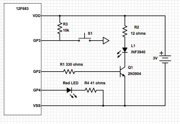
I have slightly updated the schematic since my last post to make the virtual wall a little more useful in my own scenario. First, I added a red LED to flash periodically to let me know the virtual wall is on. Second, I added a momentary switch for power control and setting run duration. When the device isn’t running, it’s not really off, rather in a sleep state that should only consume a trivial amount of power. When the button is first pressed, it wakes up the microprocessor and sets the run time to some default duration (currently about three hours). Pressing the button when the device is already running will add another hour to the run time, up to a maximum of about 10 hours. My Roomba isn’t fancy enough to allow for scheduling, so hitting the button on the virtual wall on my way to turn on the Roomba is no big deal, and this should help me get the most out of my batteries.
Code
The biggest update in my code from the last pass is the addition of an interrupt handler for reacting to button presses. This handler determines how long the device will stay awake and continue to send IR pulses.
I’ve also set the BURST_COUNT to a value of 100. The BURST_COUNT is the number of IR bursts will be sent before the microprocessor takes a short nap to preserve battery life. In my previous code, I had the value set at 10, which worked in my initial tests. However, I was having a problem with reliability, so I set it to 100 and left it there. It’s probably worth fiddling with, but even when it’s set to 100, bursts are sent for 200ms, followed by a 272ms sleep state. This means that the microprocessor is still spending more time dozing than working.
| 1 2 3 4 5 6 7 8 9 10 11 12 13 14 15 16 17 18 19 20 21 22 23 24 25 26 27 28 29 30 31 32 33 34 35 36 37 38 39 40 41 42 43 44 45 46 47 48 49 50 51 52 53 54 55 56 57 58 59 60 61 62 63 64 65 66 67 68 69 70 71 72 73 74 75 76 77 78 79 80 81 82 83 84 85 86 87 88 89 90 91 92 93 94 95 96 97 98 99 100 101 102 103 104 105 106 107 108 109 110 111 112 113 114 115 116 117 118 119 120 121 122 123 |
|
Enclosure
As I had predicted, getting this project into an enclosure was my biggest hurdle. I bought a project enclosure from RadioShack for about $5 to use as a starting point and was able to get everything mounted in there pretty well, including the proto board, status LED and switch. I originally had the IR LED soldered onto my board, and I used a small piece black tubing that extended from the front of the enclosure and over the IR LED to try to give the infrared light some direction. My experimentation with this method didn’t prove to be very successful. In hindsight, however, I think it may have been more of a software problem.
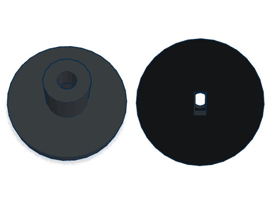
Nonetheless, having just had a positive experience with 3D printing, I tried another route for mounting the IR LED. I measured the width and depth of the IR output hole on a real virtual wall and tried to create something simple and cheap to reproduce it. What I came up with is a little IR LED holder that cost me less than $1 to print. The part is pushed through a hole on the front of the enclosure and holds the IR LED in place while creating an output path similar to the actual virtual wall. I won’t claim that it’s pretty to look at. In fact, the printed part I ended up with is flawed in that it doesn’t exactly match the model’s dimensions, but it’s good enough. You can view, modify and download a model of the IR LED socket here.
IR LED Holder
Finished Product
I spent about $8 specifically for this project, which includes the enclosure, the battery holder, and the 3D-printed IR LED socket. The rest of the components were already part of my stock of nerd stuff, and probably have a value of about $3 to $5. This makes it less expensive than an OEM virtual wall,provided you don’t count all the hours I spent building, coding, experimenting. You can’t put a price on fun though, right?
Here you can see the virtual wall in action at doorway between my dining room and the kitchen, precisely where it is meant to live out its days. You’ll notice at about the five second mark, the Roomba starts to enter the kitchen, but does an about-face when it hits the virtual wall’s IR beam. The testing I’ve done seems to indicate a reliable range of about 10 feet, though modifying the BURST_COUNT constant in the code and using a better IR LED socket might improve on that slightly.
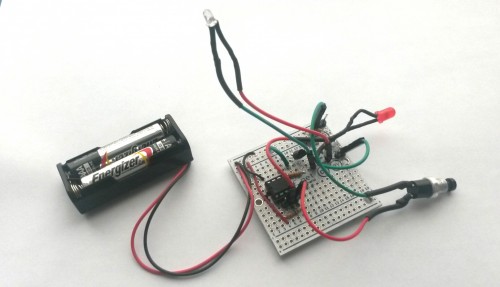
This is the entire circuit and all the components soldered onto a perma-proto board.
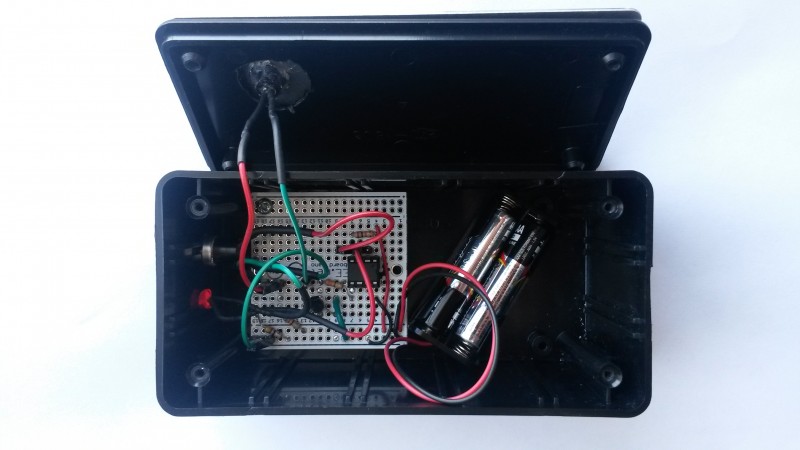
Everything installed in the enclosure. I drove a single screw through an unused portion of the perma-proto board to hold it steady. The battery holder is free to flop about, which is fine for this application. Ignore the really ugly cut on the inside plastic cover. Just pretend like you didn’t even see it.
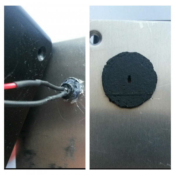
This is the 3D-printed IR LED socket from the inside and out. The final print didn’t quite match the original model, but it seems to be working well enough. I used hot glue to affix it to the enclosure.
http://misc.ws/2014/08/09/diy-virtual-wall-for-roomba-part-two/