前言
串口通信是一种设备间常用的串行通信方式,因为它简单便捷,大部分设备支持该通信方式。今天使用一个ttl转usb模块连接usart1和调试助手通信。
一、串口的基本介绍
1. 简介
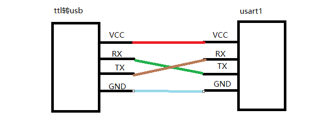
串口通信涉及USART。TX,RX,GND三根线就可以完成串口助手和STM32的通信。其中本次实验需要将ttl转usb模块的tx和rx引脚与板子上的交叉接上。如图:
2. 串口协议
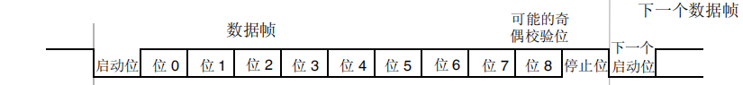
一个数据包,包括1位起始位,5-8位数据位,1位校验位,0.5-2个停止位,起始位一般为0,停止位的电平为1。
二、
1. 配置步骤
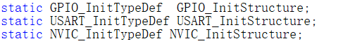
我们需要配置三个结构体,分别是GPIO,USART,NVIC;这个和之前的外部中断配置有点像,其中也需要配置一个中断函数(接收中断)。
2. 完整代码
代码如下:
#include "stm32f4xx.h"                  // Device header
#include "sys.h"
#include "stdio.h"
#include "stm32f4xx_usart.h"

static GPIO_InitTypeDef  GPIO_InitStructure;
static USART_InitTypeDef USART_InitStructure;
static NVIC_InitTypeDef NVIC_InitStructure;


struct __FILE {

     int handle; /* Add whatever you need here */ };
FILE __stdout;
FILE __stdin;
int fputc(int ch, FILE *f)
{


	USART_SendData(USART1,ch);
	while(USART_GetFlagStatus(USART1,USART_FLAG_TC)==RESET);
	USART_ClearFlag(USART1,USART_FLAG_TC);
	return ch;
}


void delay_ms(uint32_t n)
{


	while(n--)
	{


		SysTick->CTRL = 0; // Disable SysTick
		SysTick->LOAD = (168000)-1; // Count from 255 to 0 (256 cycles)
		SysTick->VAL = 0; // Clear current value as well as count flag
		SysTick->CTRL = 5; // Enable SysTick timer with processor clock
		while ((SysTick->CTRL & 0x00010000)==0);// Wait until count flag is set
	}

	SysTick->CTRL = 0; // Disable SysTick
}


void usart1_init(uint32_t bound)
{


	//打开硬件时钟
	RCC_AHB1PeriphClockCmd(RCC_AHB1Periph_GPIOA, ENABLE);

	//打开串口1硬件时钟
	RCC_APB2PeriphClockCmd(RCC_APB2Periph_USART1, ENABLE);

	//配置PA9和PA10为服用功能
	GPIO_InitStructure.GPIO_Pin = GPIO_Pin_9|GPIO_Pin_10;
	GPIO_InitStructure.GPIO_Mode = GPIO_Mode_AF;//复用功能模式
	GPIO_InitStructure.GPIO_OType = GPIO_OType_PP;//推挽输出
	GPIO_InitStructure.GPIO_Speed = GPIO_Speed_100MHz;//100MHz
	GPIO_InitStructure.GPIO_PuPd = GPIO_PuPd_UP;//上拉
	GPIO_Init(GPIOA, &GPIO_InitStructure);//初始化


	//将PA9和PA10引脚连接到串口1的硬件
	GPIO_PinAFConfig(GPIOA,GPIO_PinSource9,GPIO_AF_USART1);
	GPIO_PinAFConfig(GPIOA,GPIO_PinSource10,GPIO_AF_USART1);

	//配置串口1相关参数:波特率、无校验位、8位数位、1位停止位
	USART_InitStructure.USART_BaudRate = bound;//波特率设置
	USART_InitStructure.USART_WordLength = USART_WordLength_8b;//字长为8位数据格式
	USART_InitStructure.USART_StopBits = USART_StopBits_1;//一个停止位
	USART_InitStructure.USART_Parity = USART_Parity_No;//无奇偶校验位
	USART_InitStructure.USART_HardwareFlowControl = USART_HardwareFlowControl_None;//无硬件数据流控制
	USART_InitStructure.USART_Mode = USART_Mode_Rx | USART_Mode_Tx; //收发模式
	USART_Init(USART1, &USART_InitStructure); //初始化串口1


	//配置串口1的中断触发方法 接收一个字节触发中断
	USART_ITConfig(USART1, USART_IT_RXNE, ENABLE);

	//配置串口1的中断优先级
	NVIC_InitStructure.NVIC_IRQChannel = USART1_IRQn;//串口1中断通道
	NVIC_InitStructure.NVIC_IRQChannelPreemptionPriority=3;//抢占优先级3
	NVIC_InitStructure.NVIC_IRQChannelSubPriority =3; //子优先级3
	NVIC_InitStructure.NVIC_IRQChannelCmd = ENABLE; //IRQ通道使能
	NVIC_Init(&NVIC_InitStructure); //根据指定的参数初始化VIC寄存器


	//使能串口1工作
	USART_Cmd(USART1,ENABLE);
}


int main(void)
{


	RCC_AHB1PeriphClockCmd(RCC_AHB1Periph_GPIOF, ENABLE);//使能GPIOF时钟

	//GPIOF9,F10初始化设置
	GPIO_InitStructure.GPIO_Pin = GPIO_Pin_9;
	GPIO_InitStructure.GPIO_Mode = GPIO_Mode_OUT;//复用功能模式
	GPIO_InitStructure.GPIO_OType = GPIO_OType_PP;//推挽输出
	GPIO_InitStructure.GPIO_Speed = GPIO_Speed_100MHz;//100MHz
	GPIO_InitStructure.GPIO_PuPd = GPIO_PuPd_UP;//上拉
	GPIO_Init(GPIOF, &GPIO_InitStructure);//初始化


	GPIO_SetBits(GPIOF,GPIO_Pin_9);

	usart1_init(115200);

	printf("123\r\n");

	while(1)
	{


	}
}


void USART1_IRQHandler(void)
{


	char d;
	//检查标志位
	if(USART_GetITStatus(USART1, USART_IT_RXNE) != RESET) //接收中断
	{


		d=USART_ReceiveData(USART1);


		USART_SendData(USART1,d);
		//清空标志位
		USART_ClearITPendingBit(USART1,USART_IT_RXNE);
	}


}