The idea of this program is the simplest and does not involve complex algorithms: identify the rectangular frame, mark the rectangular frame, output the coordinates and center point, calculate the length, and control the steering gear to move a fixed length! It is only for reference to complete basic functions, don’t spray if you don’t like it!
# Realize motion target control and automatic tracking system
## Task overview
This article will introduce how to use the OpenMV development board and steering gear to build a moving target control and automatic tracking system. The system includes a red spot position control system that simulates target movement and a green spot position control system that indicates automatic tracking. Through the implementation of this article, we can identify the target in the image, control the servo to move along the target, and output the center position and length of the target rectangle.
## Hardware preparation
1. OpenMV H7 Plus development board
2. Red and green laser pointer
3. Two servos (connected to OpenMV development board)
## Hardware connection
Connect the two servos to the servo pins of the OpenMV development board (choose according to the actual pins).
## Camera Settings
In the code, we set the camera to QVGA resolution and RGB565 format.
import sensor, image, math, pyb

# 初始化相机
sensor.reset()
sensor.set_pixformat(sensor.RGB565)
sensor.set_framesize(sensor.QVGA)
sensor.skip_frames(time=2000)

# 其他代码...
## Target detection and tracking (target detection part of the code has been tested!)
### Find rectangle function
In order to identify the target rectangle in the image, we need to write a find rectangle function. This function will return the second largest rectangular area so we can find where the target is.
# 寻找矩形函数,返回第二大的矩形区域
def find_second_largest_rectangle(blobs):
    max_area = 0
    max_blob = None
    second_max_area = 0
    second_max_blob = None

    for blob in blobs:
        area = blob.area()
        if area > max_area:
            second_max_area = max_area
            second_max_blob = max_blob
            max_area = area
            max_blob = blob
        elif area > second_max_area:
            second_max_area = area
            second_max_blob = blob

    return second_max_blob
## Main loop
In the main loop, we will continuously acquire images and do object detection and tracking.
while True:
    img = sensor.snapshot() # 获取图像
    blobs = img.find_blobs([black_threshold], pixels_threshold=200, area_threshold=200)

    if blobs:
        # 寻找第二大的矩形区域
        second_max_blob = find_second_largest_rectangle(blobs)
        if second_max_blob:
            img.draw_rectangle(second_max_blob.rect(), color=(255, 0, 0), thickness=4) # 绘制第二大的矩形框,颜色为红色

            # 其他代码...
## Servo Control
In order to achieve target tracking, we need to control the servo to move around the rectangle and return to the center. Here we use `pyb.Servo()` to control the movement of the servo.
# 舵机参数
servo_pan_pin = 1 # 舵机1的引脚编号
servo_tilt_pin = 2 # 舵机2的引脚编号
servo_pan = pyb.Servo(servo_pan_pin) # 初始化舵机1
servo_tilt = pyb.Servo(servo_tilt_pin) # 初始化舵机2
servo_speed = 50 # 舵机转动速度(0-100,越大越快)
servo_pan_range = (0, 180) # 舵机1转动范围(角度)
servo_tilt_range = (0, 180) # 舵机2转动范围(角度)

# 控制舵机沿着矩形框移动一圈,并回到中心点
for angle in range(servo_pan_range[0], servo_pan_range[1], servo_speed):
    servo_pan.angle(angle) # 控制舵机1水平旋转
    servo_tilt.angle(angle) # 控制舵机2垂直旋转
    pyb.delay(100) # 延时一段时间,控制舵机转动速度

# 将舵机回到中心点
servo_pan.angle((servo_pan_range[0] + servo_pan_range[1]) // 2)
servo_tilt.angle((servo_tilt_range[0] + servo_tilt_range[1]) // 2)
## Result output
After detecting the target, we will output the center position and length of the target rectangle. At the same time, we will mark the position of the rectangle in the image. (The test coordinates and length are still relatively prepared)
# 获取矩形框的中心点坐标
x, y = second_max_blob.cx(), second_max_blob.cy()

# 计算矩形框的长度和宽度(单位:厘米)
width_cm = 2 * distance_cm * math.tan(math.radians(H_FOV / 2)) * (second_max_blob.w() / img.width())
height_cm = 2 * distance_cm * math.tan(math.radians(V_FOV / 2)) * (second_max_blob.h() / img.height())

# 输出矩形框的中心点坐标和长度(单位:厘米)
print("Rectangle Center Coordinates (cm): x={}, y={}".format(x, y))
print("Rectangle Width (cm): {}, Height (cm): {}".format(width_cm, height_cm))

# 绘制黄色圆点标记矩形框中心位置
img.draw_circle(x, y, 5, color=(255, 255, 0), thickness=2)
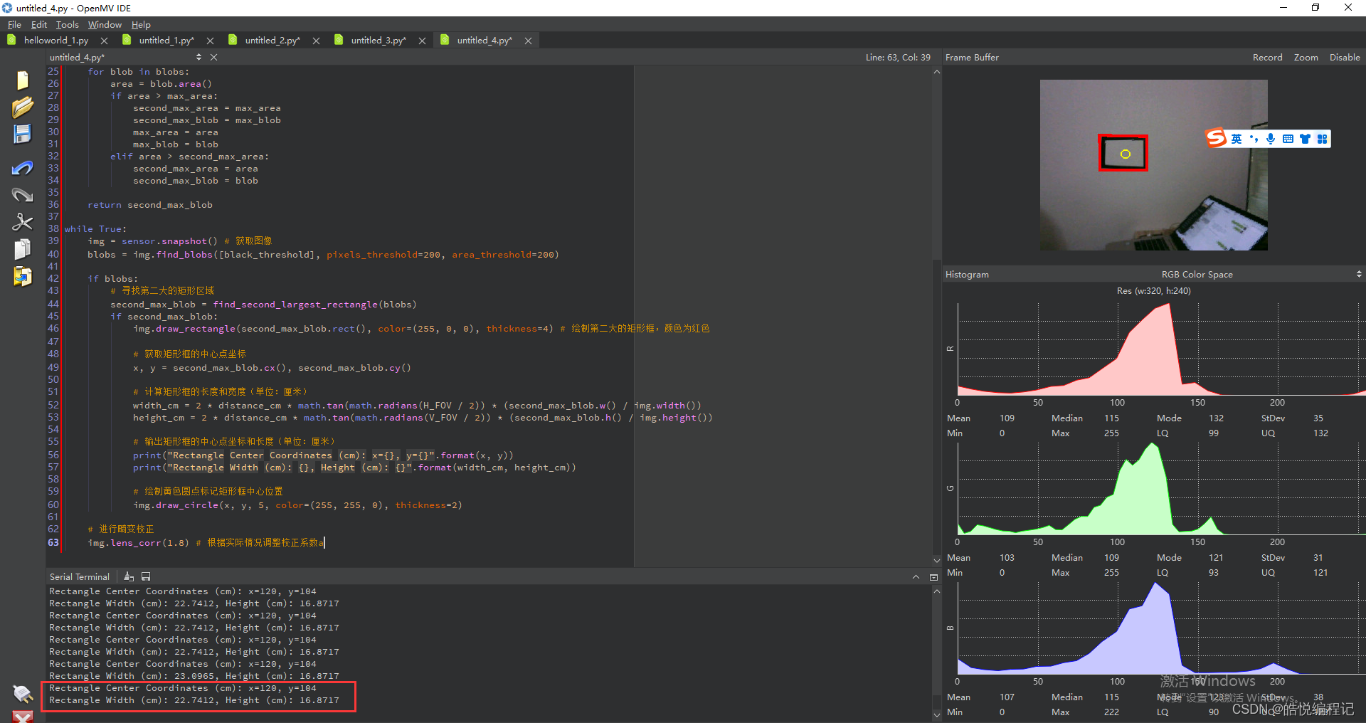
## Running effect
After connecting the hardware, upload the code to the OpenMV development board, and adjust the servo parameters and position. After running the code, you will see the servo move along the target rectangle, and mark the position and center of the rectangle in the image.
## Conclusion
Through the implementation of this article, we have successfully built a moving target control and automatic tracking system. By using the OpenMV development board and servos, we are able to identify the target in the image and control the servos to track the target.
## Reference link
1. OpenMV official website: https://openmv.io/
2. Pyb Servo document: https://docs.openmv.io/library/pyb.Servo.html
We welcome your valuable comments and suggestions to discuss learning and improvement together. thanks for reading!