倾斜式开关
const int sigPin =7;
const int ledPin =13;
boolean sigState =0;

void setup()
{
    pinMode(ledPin,OUTPUT);
    pinMode(sigPin,INPUT);
    Serial.begin(9600);
}

void loop()
{
  sigState =digitalRead(sigPin);
  Serial.println(sigState);

  if(sigState==HIGH)
  {
    //trun LED off
    digitalWrite(ledPin,LOW);
  }
  else
  {
    //turn LED on
    digitalWrite(ledPin,HIGH);
  }
}
倾斜式开关:在倾斜开关中球以不同的倾斜角度以制造触发器电路原理。倾斜开关模块使用双向传导的球形倾斜开关。当它向任一侧倾斜时,只要倾斜和力满足条件,开关就会通电;输出低电平信号。
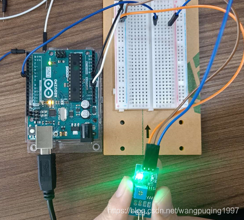
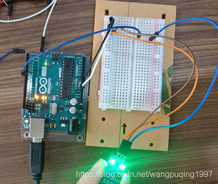
震动开关
int vibswPin =8;
int ledPin =13;
int val =0;
void setup()
{
  pinMode(vibswPin,INPUT);
  pinMode(ledPin,OUTPUT);
  Serial.begin(9600);
}

void loop()
{
  val = digitalRead(vibswPin);
  Serial.println(val);
  if(val == LOW)
  {
    //trun ON the led
    digitalWrite(ledPin,HIGH);
    delay(500);
  }
  else
  {
    //trun OFF the led
    digitalWrite(ledPin,LOW);
  }
}
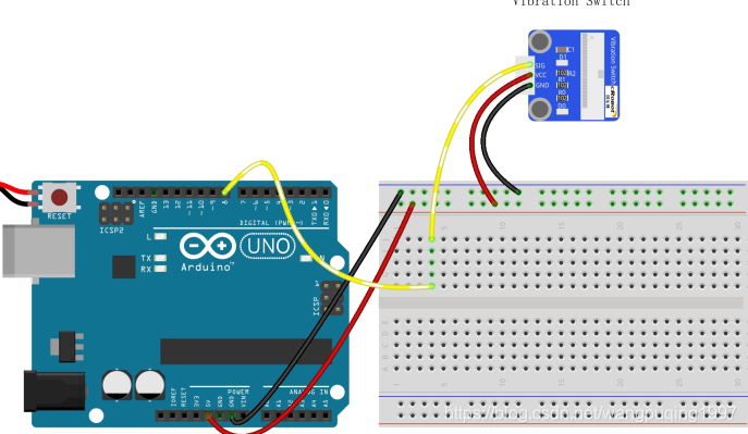
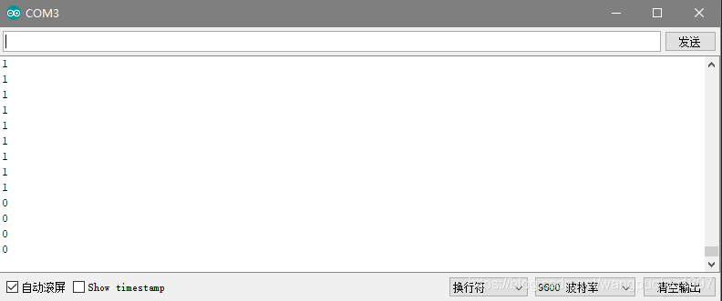
从串口监视里可以看到当传感器受到震动时,收到高电平信号。
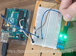
干簧管传感器
/*****************************************************
 * name:Reed Switch
 * function:use a magnet to approach the reed switch, and the LED on the reed switch module and that on the Arduino board light up.
 * Move the magnet farther and the LED will go out.
 **************************************************/

const int digitalInPin = 7;// reed switch attach to pin7
const int ledPin = 13;// pin13 built-in led

void setup()
{
  pinMode(digitalInPin,INPUT);// set digitalInPin as INPUT
  pinMode(ledPin,OUTPUT); // set ledPin as OUTPUT
}

void loop()
{
  boolean stat = digitalRead(digitalInPin);//read the value of pin7 to stat
  if(stat == HIGH)// if it it HIGH
  {
    digitalWrite(ledPin,LOW);// then turn off the led
  }
  else //else
  {
    digitalWrite(ledPin,HIGH); // turn on the led
  }
}
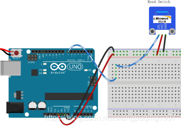
干簧管传感器是一种通过磁信号实现控制的线路开关组件,它能感应磁铁的存在。这里的“开关”是指干簧管,它是一种结构简单,体积小,控制方便的接触式无源电子开关元件,干簧管壳体一般为密封玻璃管,配备弹性簧片电镀,并填充惰性气体,通常玻璃管中由特殊材料制成的两个簧片是分开的,但当磁性物质靠近玻璃管时,玻璃管中的两个簧片被磁化吸引其他的在磁场线的作用下接触,这样两个簧片就会拉在一起。
在外部磁力消失后,两个簧片由于具有相同的磁性而相互分离,因此电路也断开。因此作为通过在磁信号控制的线路开关部件,干簧管可以作传感器来计数,限制位置等,广泛用于通讯设备。
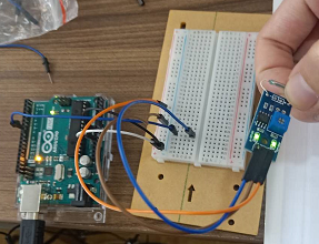
U型光电传感器
/**********************************/
const int photoPin = 7; //the number of the key pin
const int ledPin = 13;//the number of the led pin
/**********************************/
void setup()
{
  pinMode(photoPin,INPUT);
  pinMode(ledPin,OUTPUT);//initialize the led pin as output
}
/**********************************/
void loop()
{

  boolean Value=digitalRead(photoPin);

  //if it is,the state is HIGH
  if(Value ==HIGH )
  {
    digitalWrite(ledPin,LOW);//turn on the led
  }
  else
  {
    digitalWrite(ledPin,HIGH);//turn off the led
  }
}
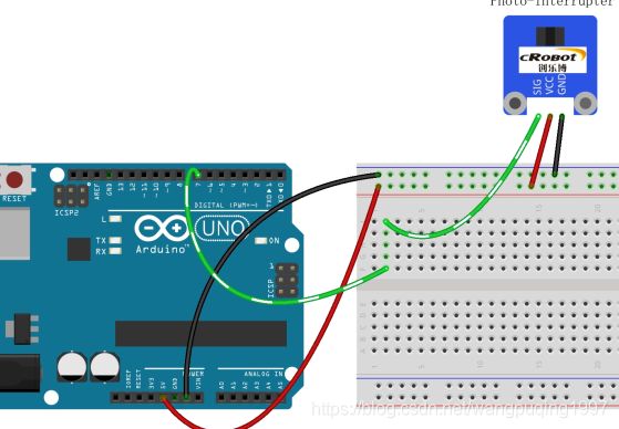
U型光电传感器由两部分组成:发射器和接收器。发射器(例如LED,激光器)发出的光,然后光线进入接收器。如果发射器和接受器之间的光束被障碍物挡住,接收器即使在一瞬间也将检测不到射光,并且输出电平将会改变。
PCF8591模数转换器
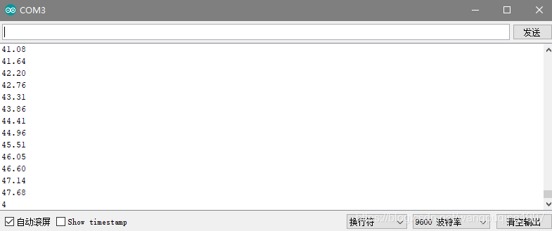
/***********************************************
name:Analog-Digital Converter -PCF8591
function:the indicator light D2 on the  PCF8591 gradually lights up and goes out alternately.
The same happens to the LED attached to pin 13 of the Arduino Uno board
***************************************************/

#include "Wire.h" //Wire库
#define PCF8591 (0x90 >> 1) // I2C总线的地址
void setup()
{
 Wire.begin();
 Serial.begin(9600);
 Serial.println(sin(PI/2));

}
void loop()
{
 for (int i=0; i<256; i++)
 {
 Wire.beginTransmission(PCF8591); // 唤醒 PCF8591
 Wire.write(0x40); // control byte - turn on DAC (binary 01000000),analog OUTPUT DAC转换
 Wire.write(i); // value to send to DAC
 Wire.endTransmission(); // end tranmission
 delay(10*sin(i/256.0*90/180*PI));
 Serial.println(100*sin(i/256.0*90/180*PI));
 }

 for (int i=255; i>=0; --i)
 {
 Wire.beginTransmission(PCF8591); // wake up PCF8591
 Wire.write(0x40); // control byte - turn on DAC (binary 1000000)
 Wire.write(i); // value to send to DAC
 Wire.endTransmission(); // end tranmission
 delay(10*sin(i/256.0*90/180*PI));
 Serial.println(100*sin(i/256.0*90/180*PI));
 }
}
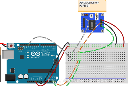
PCF8591是一种具有I2C总线接口的A/D转换芯片。在与CPU的信息传输过程中仅靠时钟线SCL和数据线SDA就可以实现。
PCF8591是具有I2C总线接口的8位A/D及D/A转换器。有4路A/D转换输入,1路D/A模拟输出。这就是说,它既可以作A/D转换也可以作D/A转换。A/D转换为逐次比较型。
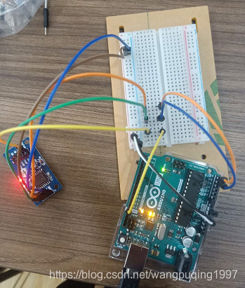
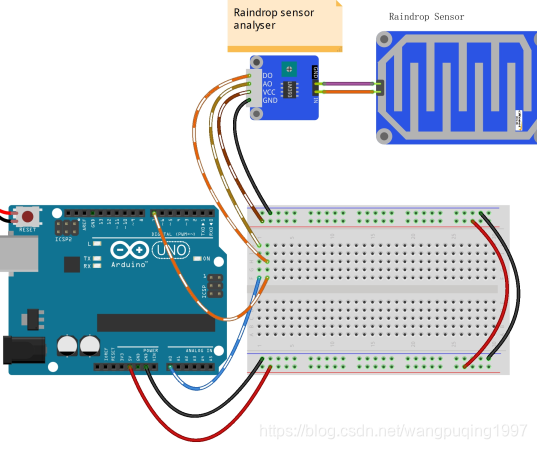
雨滴探测传感器
/******************************************************
name:Raindrop Detection
function:drop some water onto the sensor,
When the quantities of the raindrops exceeds the threshold,
the LED on the raindrop sensor module and that hooked up with pin 13 of the Arduino Uno board light up
*******************************************************/

const int analogPin=A0; //the AO of the module attach to A0
const int digitalPin=7;  //D0 attach to pin7
const int ledPin=13;  //pin 13 built-in led
int Astate=0; //store the value of A0
boolean Dstate=0;  //store the value of D0

void setup()
{
 pinMode(ledPin,OUTPUT); //set the ledPin as OUTPUT
 pinMode(digitalPin,INPUT);  //set digitalPin as INPUT
 Serial.begin(9600);  //initialize the serial monitor
}

void loop()
{
  Astate=analogRead(analogPin);  //read the value of A0
  Serial.print("A0: ");
  Serial.println(Astate);  //print the value in the serial monitor
  Dstate=digitalRead(digitalPin);  //read the value of D0
  Serial.print("D0: ");
  Serial.println(Dstate);
  if(Dstate==HIGH)
  {
   digitalWrite(ledPin,LOW);
  }
  else //if the value of D0 is LOW
  {
  digitalWrite(ledPin,HIGH); //turn on the led
  }
}
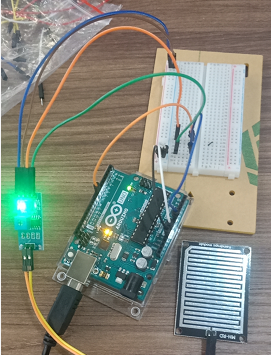
没有水滴时
有水滴时
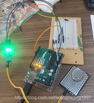
arduino板上的13引脚led和传感器上的led灯都亮起。
水越多,AO处值越低,当水滴数量超过设定的阈值时,7引脚由高电平变低电平,相应的LED将亮起。
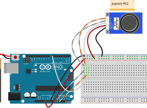
PS2操纵杆
/*********************************************
 * name:Joystick PS2
 * function:push the joystick and the coordinates of X and Y axes displayed on Serial Monitor will change accordingly;
 * press down the joystick, and the coordinate of Z=0 will also be displayed.
 connection:
 Joystick PS2                 Arduino Uno R3
 GND	                      GND
 VCC	                      5V
 SW	                      7
 x	                      A0
 y	                      A1
 ***********************************************/

const int xPin = A0;     //X attach to A0
const int yPin = A1;     //Y attach to A1
const int btPin = 7;     //Bt attach to digital 7

void setup()
{
  pinMode(btPin,INPUT); //set btpin as INPUT
  digitalWrite(btPin, HIGH); //and HIGH
  Serial.begin(9600); //initialize serial
}

void loop()
{
  Serial.print("X: ");//print "X: "
  Serial.print(analogRead(xPin),DEC); //read the value of A0 and print it in decimal
  Serial.print("\tY: "); //print "Y: "
  Serial.print(analogRead(yPin),DEC); //read the value of A1 and print it in decimal
  Serial.print("\tZ: "); //print "Z: "
  Serial.println(digitalRead(btPin)); ////read the value of pin7 and print it
  delay(100);//delay 100ms
}
打开串口监视器移动摇杆可以看到x,y,z的位置变化。
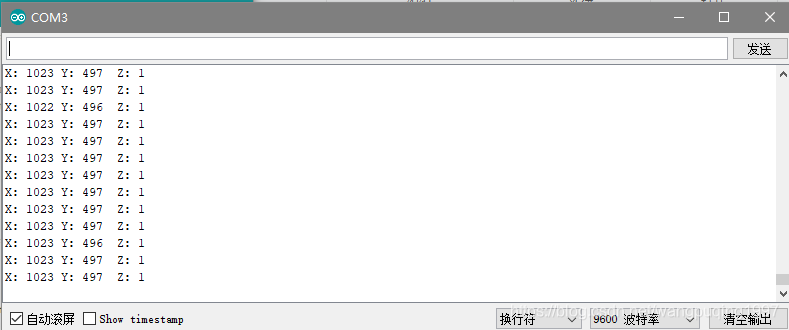
该模块具有两个模拟输出(对应于X和Y坐标)和一个数字输出,表示是否在Z轴上按下。
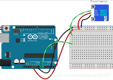
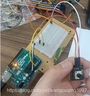
电位器
模拟电位器是模拟电子元器件。数字电位器仅指开/关,高/低电平两种状态,即0或1,而模拟电位器支持1至1000之间的模拟信号。信号值随时间变化而不是保持一个确切的数字。模拟信号包括光强度,湿度,温度等。
在本实验中,将电位器模块的引脚SIG连接到Arduino Uno电路板的AO,检查AO的值。然后使用该值来控制与Uno板的针脚13连接的LED闪烁时间间隔。旋转电位器的轴,LED闪烁间隔将增加或减少。
const int analogPin = A0;//the analog input pin attach to
const int ledPin =13;//the led attach to
int inputValue = 0;//variable to store the value coming from sensor
/******************************************/
void setup()
{
  pinMode(ledPin,OUTPUT);
  Serial.begin(9600);
}
/******************************************/
void loop()
{
  inputValue = analogRead(analogPin);//read the value from the sensor
  //Serial.println(inputValue);
  digitalWrite(ledPin,HIGH);
  delay(inputValue);
  digitalWrite(ledPin,LOW);
  delay(inputValue);
}
/*******************************************/
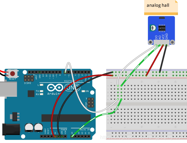
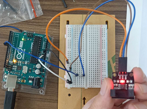
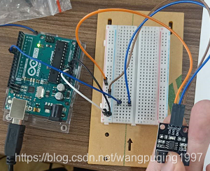
模拟霍尔传感器
模拟霍尔传感器由霍尔元件,线性放大器和射极跟随器组成,输出模拟值。如果在模拟霍尔传感器上增加比较器就可以组成数字开关霍尔传感器和模拟霍尔传感器一体,他可以输出模拟值和数字信号。
当传感器靠近磁体,引脚A0的值将改变。当该值超过电位器设定的阈值之前,D0將输出低电平,相应的LED亮起。
//Analog Hall Sensor
//using an LM393 Low Power Low Offset Voltage Dual Comparator
/*******************************
 * Analog Hall Sensor     Uno R3
 * A0                     A0
 * D0                     7
 * VCC                    5V
 * GND                    GND
 *******************************/

const int ledPin = 13;//the led attach to pin13
int sensorPin = A0;    // select the input pin for the potentiometer
int digitalPin=7;   //D0 attach to pin7

int sensorValue = 0;// variable to store the value coming from A0
boolean digitalValue=0;// variable to store the value coming from pin7

void setup()
{
  pinMode(digitalPin,INPUT);//set the state of D0 as INPUT
  pinMode(ledPin,OUTPUT);//set the state of pin13 as OUTPUT
  Serial.begin(9600); // initialize serial communications at 9600 bps

}

void loop()
{
  sensorValue = analogRead(sensorPin);  //read the value of A0
  digitalValue=digitalRead(digitalPin);  //read the value of D0
  Serial.print("Sensor Value "); // print label to serial monitor
  Serial.println(sensorValue);  //print the value of A0
  Serial.print("Digital Value "); // print label to serial monitor
  Serial.println(digitalValue);  //print the value of D0 in the serial
  if( digitalValue==HIGH )//if the value of D0 is HIGH
  {
    digitalWrite(ledPin,LOW);//turn off the led
  }
  if( digitalValue==LOW)//else
  {
    digitalWrite(ledPin,HIGH);//turn on the led
  }
  delay(1000);//delay 200ms
}