【f1c200s/f1c100s】RGB接口 LCD驱动适配
RGB模式介绍
RGB 模式就是我们通过说的 RGB 屏,以 RGB(TTL 信号)并行数据线传输,广泛的应用于 5 寸及以上的 TFT-LCD 中。引脚包含RGB数据+时钟+控制引脚;数据位数可为:RGB565、RGB666、RGB888,数据位树越多,颜色失真就越少。
| 信号线 | 描述 |
|---|---|
| R[7:0] | 8 根红色数据线 |
| G[7:0] | 8 根绿色数据线 |
| B[7:0] | 8 根蓝色数据线 |
| DE | 数据使能线 |
| VSYNC | 垂直同步信号线 |
| HSYNC | 水平同步信号线 |
| PCLK | 像素时钟信号线 |
由于每一块屏幕分辨率、时序参数不一样(其实差距不大,所以参数有时候设置不完全正确也能点亮屏幕),每一块屏幕的参数都必须重新配置。幸运的是,linux内核已经适配了RGB模式下的LCD驱动(见drivers/gpu/drm/panel/panel-simple.c),我们不需要从零写一个屏幕驱动,所以我们只需要简单几步即可驱动LCD屏幕。
F1C200s/F1C100s RGB LCD驱动适配
基于的硬件为自己设计的Mangopi和正点原子7寸LCD显示屏,分辨率为840x480。
软件在荔枝派官方代码基础上进行修改。
设备树修改
在suniv-f1c100s.dtsi中将连接LCD的引脚复用为lcd功能:
pio: pinctrl@1c20800 {


			compatible = "allwinner,suniv-f1c100s-pinctrl";
			reg = <0x01c20800 0x400>;
			interrupts = <38>, <39>, <40>;
			clocks = <&ccu CLK_BUS_PIO>, <&osc24M>, <&osc32k>;
			clock-names = "apb", "hosc", "losc";
			gpio-controller;
			interrupt-controller;
			#interrupt-cells = <3>;
			#gpio-cells = <3>;

			uart0_pe_pins: uart0-pe-pins {


				pins = "PE0", "PE1";
				function = "uart0";
			};

			uart1_pe_pins: uart1-pe-pins {


				pins = "PA2", "PA3";
				function = "uart1";
			};
			//复用LCD为模式
			lcd_rgb666_pins: lcd-rgb666-pins {


				pins = "PD0", "PD1", "PD2", "PD3", "PD4",
				       "PD5", "PD6", "PD7", "PD8", "PD9",
				       "PD10", "PD11", "PD12", "PD13", "PD14",
				       "PD15", "PD16", "PD17", "PD18", "PD19",
				       "PD20", "PD21";
				function = "lcd";
			};

			mmc0_pins: mmc0-pins {


				pins = "PF0", "PF1", "PF2", "PF3", "PF4", "PF5";
				function = "mmc0";
			};

			key_pins: key_pins {


				pins = "PA0", "PA1";
				function = "gpio_in";
			};

			i2c0_pins: i2c0_pins {


				pins = "PE11", "PE12";
				function = "i2c0";
			};
		};
在suniv-f1c100s-mangopi.dts中修改后的panel节点如下,其中compatible 属性增加了alientek,alientek_7_inch,是为了适配驱动代码中的相应屏幕的配置。
panel: panel {
compatible = "alientek,alientek_7_inch", "simple-panel";
#address-cells = <1>;
#size-cells = <0>;
reset-gpios = <&pio 4 4 GPIO_ACTIVE_LOW>;//复位引脚
power-supply = <®_vcc3v3>;
port@0 {
reg = <0>;
#address-cells = <1>;
#size-cells = <0>;
panel_input: endpoint@0 {
reg = <0>;
remote-endpoint = <&tcon0_out_lcd>;
};
};
};
源码修改
在drivers/gpu/drm/panel/panel-simple.c文件中存在非常多厂家的屏幕参数,如:
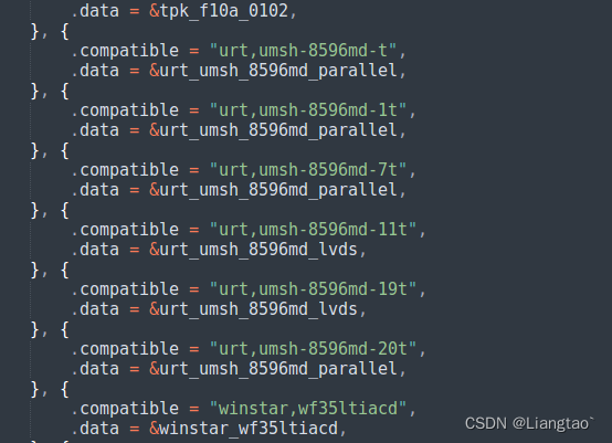
我们要做的就是在这个文件里面,仿照这些预设的参数添加我们自己的屏幕参数。
大约在2560行左右仿照上面预设的屏幕参数添加自己屏幕的时序信息,时序信息的具体含义可以参考:
Documentation/devicetree/bindings/display/panel/display-timing.txt、include/drm/drm_modes.h、RBG LCD时序参考以及自己屏幕的数据手册。
static const struct drm_display_mode alientek_7_inch_mode = {


	.clock = 51200,
	.hdisplay = 800,
	.hsync_start = 800+20,
	.hsync_end = 800 + 20 + 160,
	.htotal = 800 + 20 + 140 + 160,
	.vdisplay = 480,
	.vsync_start = 480 + 3,
	.vsync_end = 480 + 3 + 12,
	.vtotal = 480 + 3 + 12 + 20,
	.vrefresh = 60,
};

static const struct panel_desc alientek_7_inch = {


	.modes = &alientek_7_inch_mode,
	.num_modes = 1,
	.bpc = 6,
	.size = {


		.width = 154,
		.height = 85,
	},
};
然后在大约2860行左右,添加屏幕的适配信息,其中的compatible 属性需要和设备树panel中的一致。
 	{


		.compatible = "winstar,wf35ltiacd",
		.data = &winstar_wf35ltiacd,
	}, {


		.compatible = "alientek,alientek_7_inch",  //自己添加的,需要和设备树一致
		.data = &alientek_7_inch, //自己添加的
	}, {

      //末尾为空结构体,不能删除
		/* sentinel */
	}
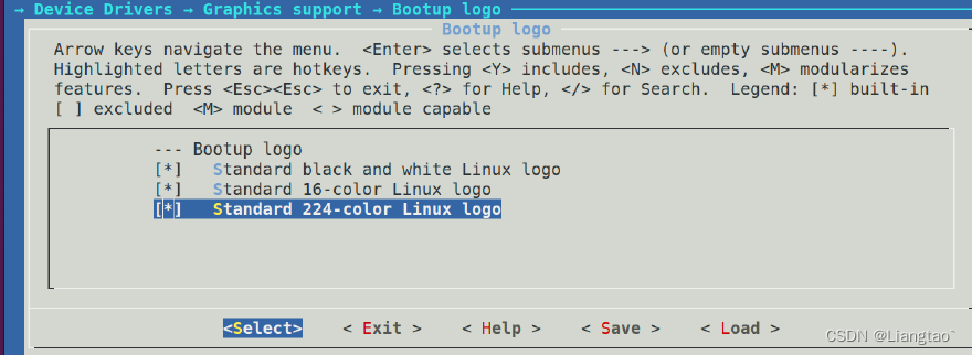
然后在menuconfig中配置打开linux logo,保存编译。
-> Device Drivers
	 -> Graphics support
		 -> Bootup logo (LOGO [=y])
		 	-> Standard black and white Linux logo
		 	-> Standard 16-color Linux logo
		 	-> Standard 224-color Linux logo
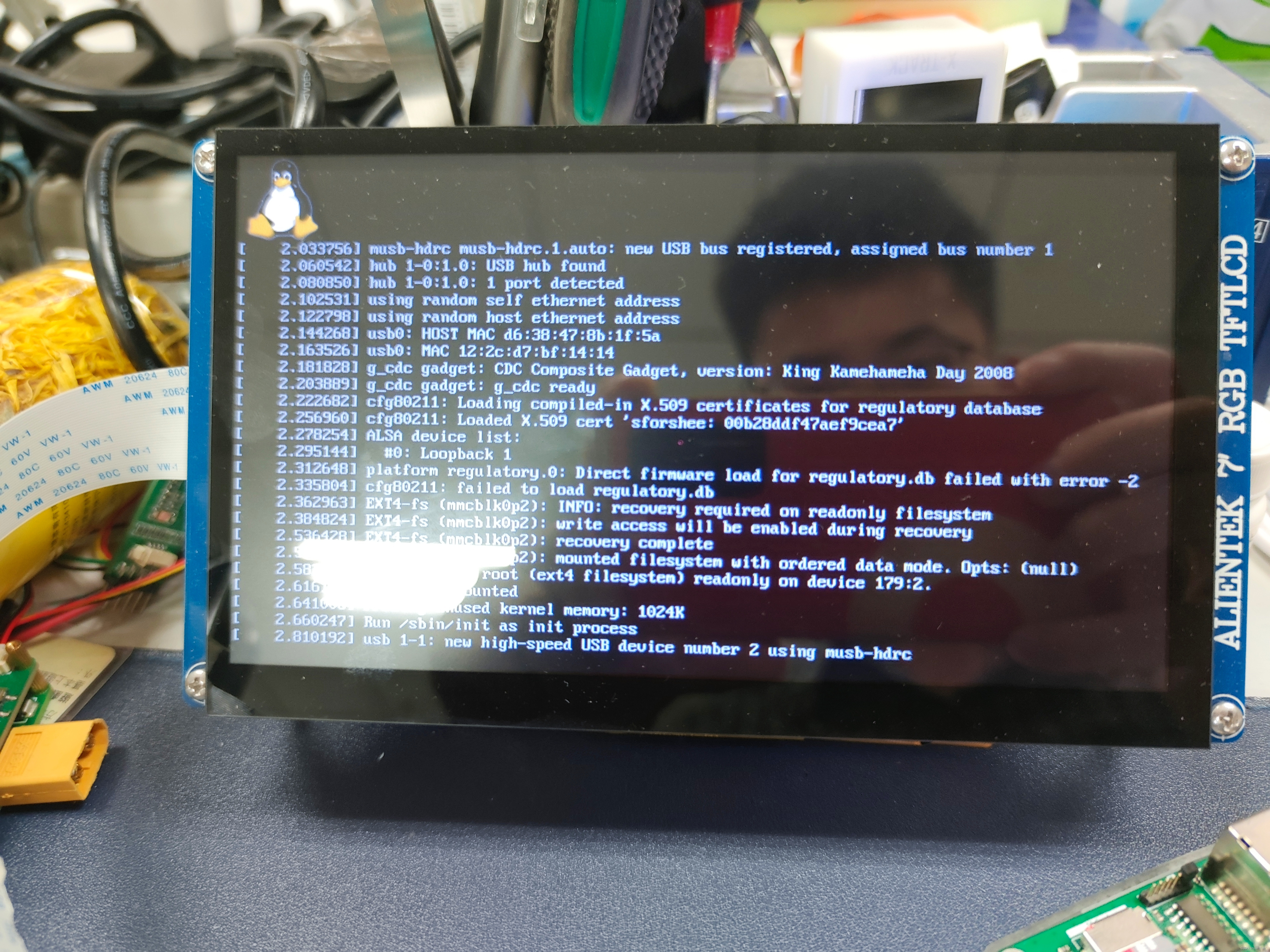
结果
不出意外在内核启动时可以看到屏幕左上角上有小企鹅logo,进入系统后可以在/dev目录下找到fb0设备。有了这个framebuffer设备之后,就可以使用lvgl或者awtk等GUI库编写漂亮的界面了。
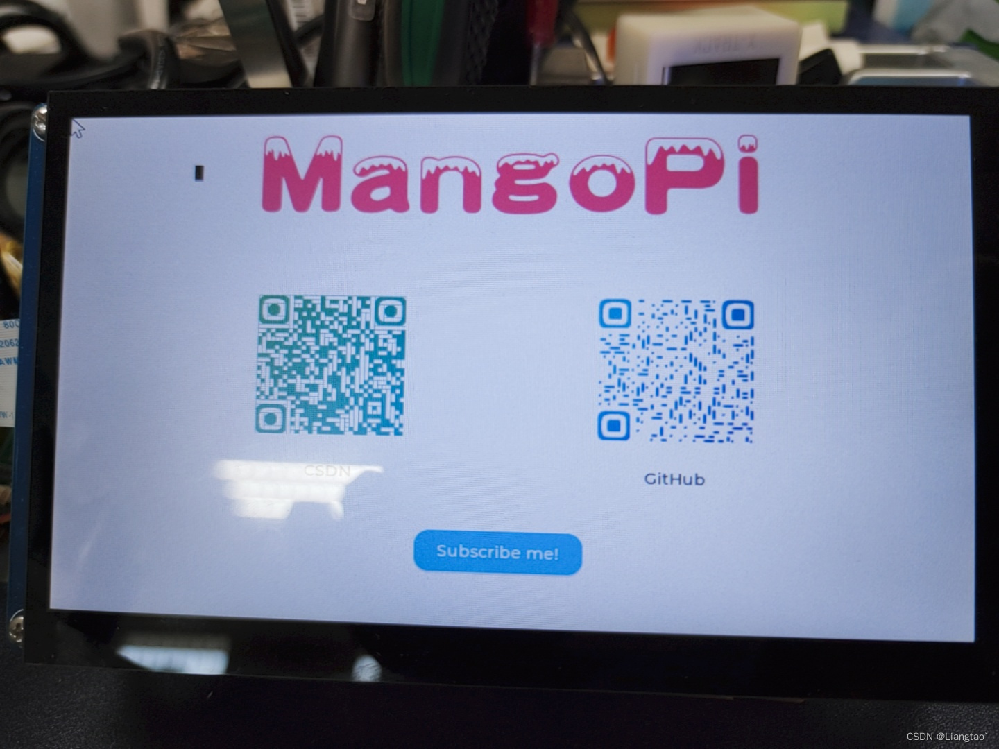
用lvgl简单写了个测试屏幕的demo: