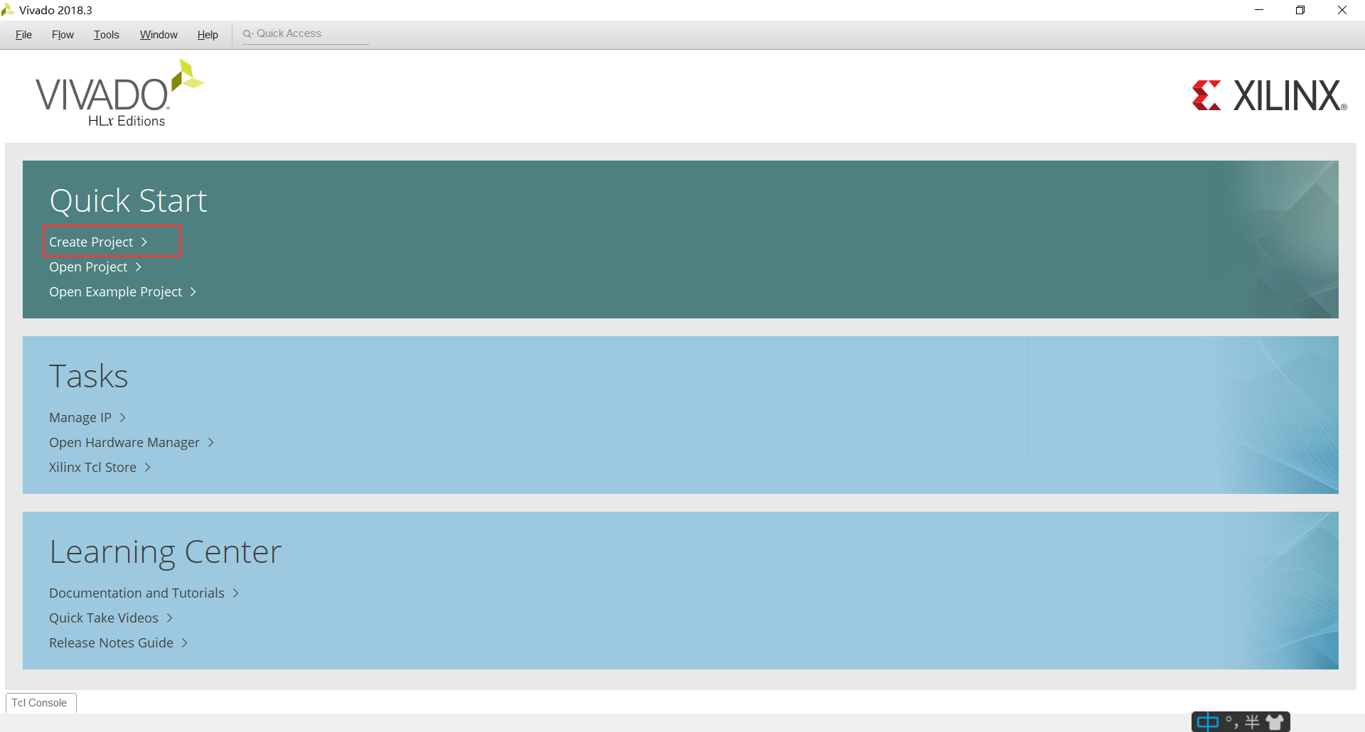
一、创建项目
Create Project:
Next:
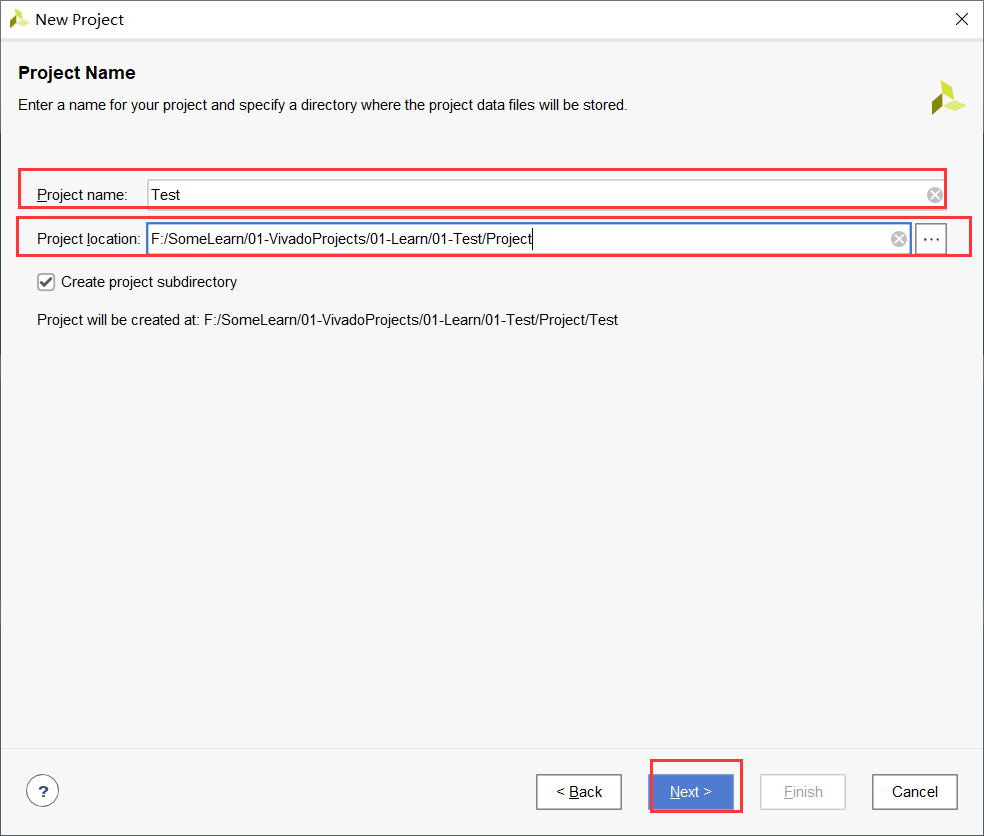
填写项目名,选择项目位置,Next:
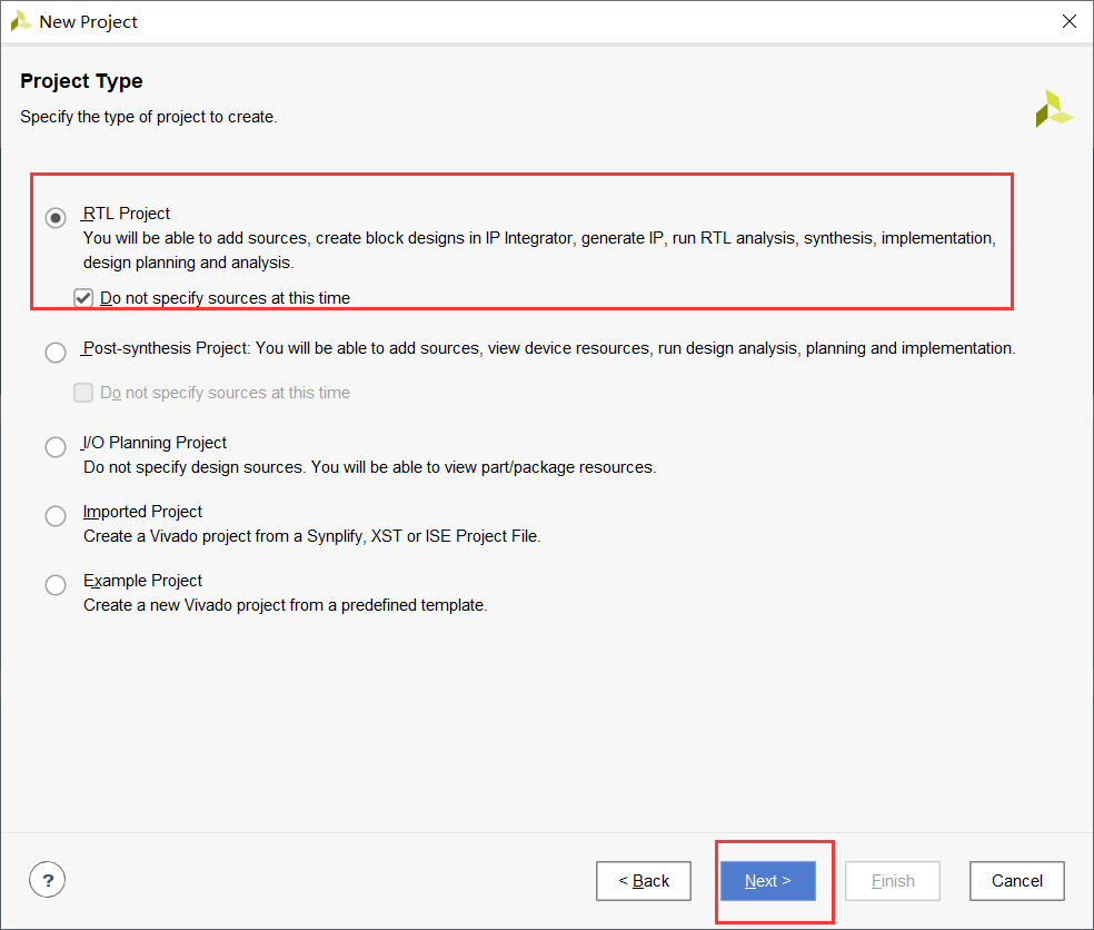
选择RTL项目,勾选Do not specify sources at the time,即不添加源文件,Next:
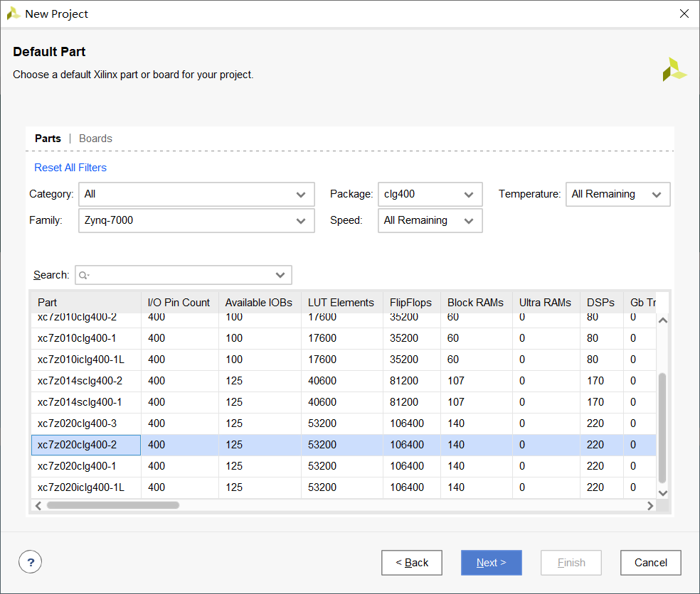
选择芯片类型,Next:
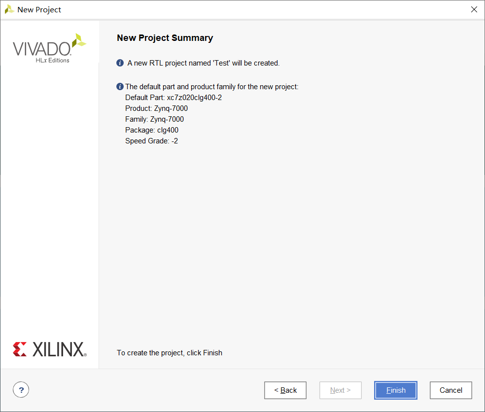
Finish:
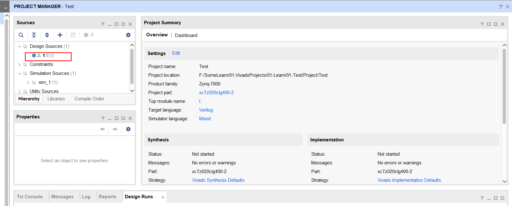
二、添加Verlog设计文件
1. 添加t.v文件
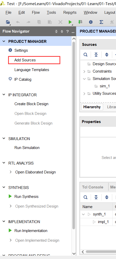
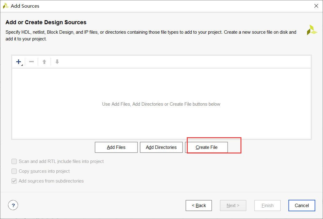
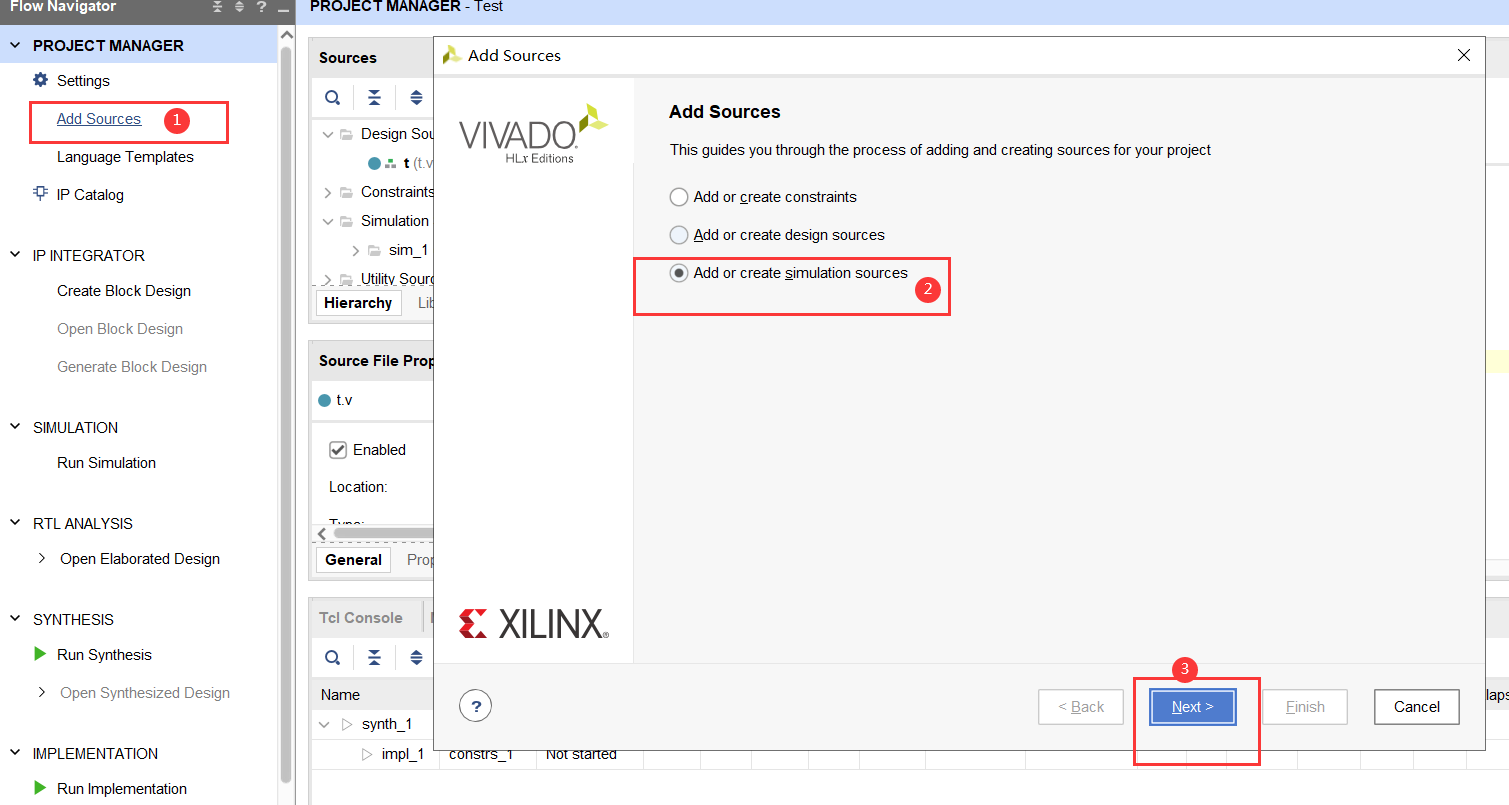
Add Sources:
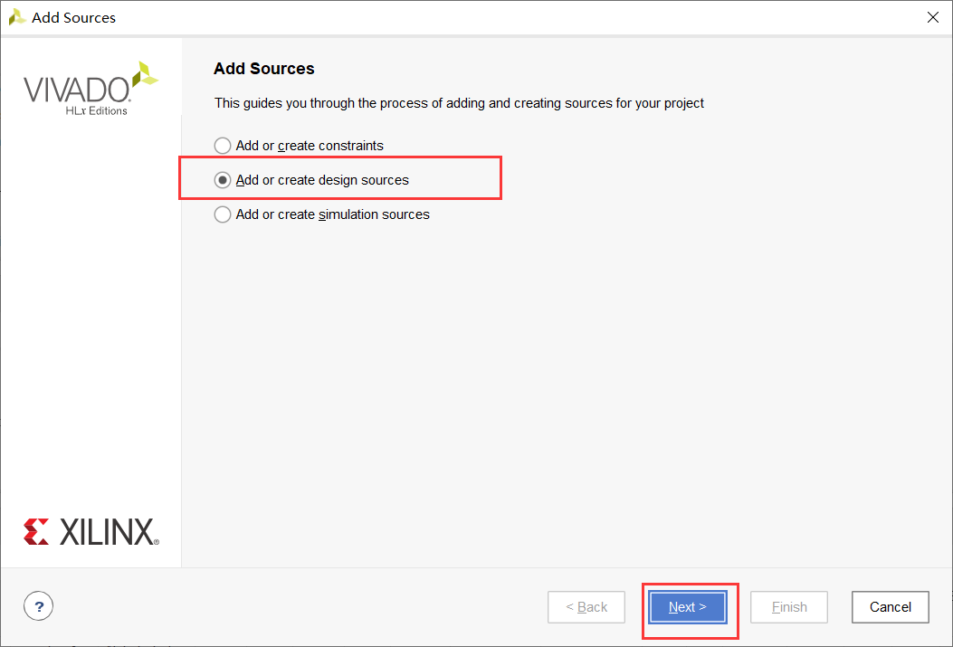
选择第二个,Next:
Create File:
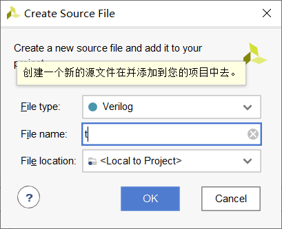
选择文件类型,填写文件名,OK:
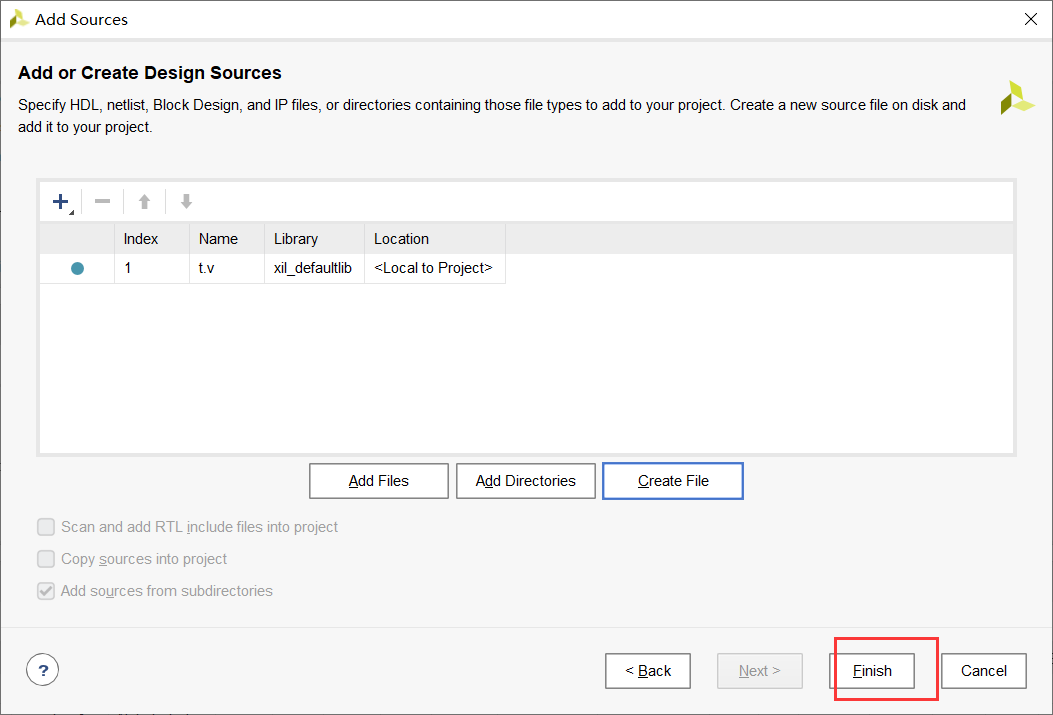
Finish:
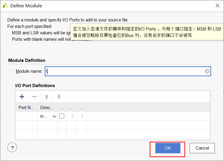
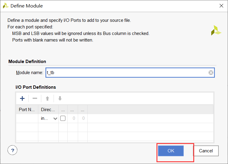
定义模块输入输出端口,暂时不设置,直接OK:
2. 编写文件
双击打开文件:
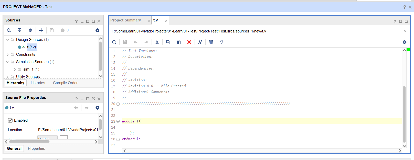
编写:
`timescale 1ns / 1ps
//
// Company:
// Engineer:
//
// Create Date: 2022/09/10 16:06:39
// Design Name:
// Module Name: t
// Project Name:
// Target Devices:
// Tool Versions:
// Description:
//
// Dependencies:
//
// Revision:
// Revision 0.01 - File Created
// Additional Comments:
//
//


module t(
    input   wire    a,
    input   wire    b,

    output  wire    c,
    output  wire    d,
    output  wire    e,
    output  wire    f
);

    assign c = ~a;
    assign d = a & b;
    assign e = a | b;
    assign f = a ^ b;


endmodule
三、添加仿真文件
1. 添加t_tb.v文件
添加仿真文件,填写名称:
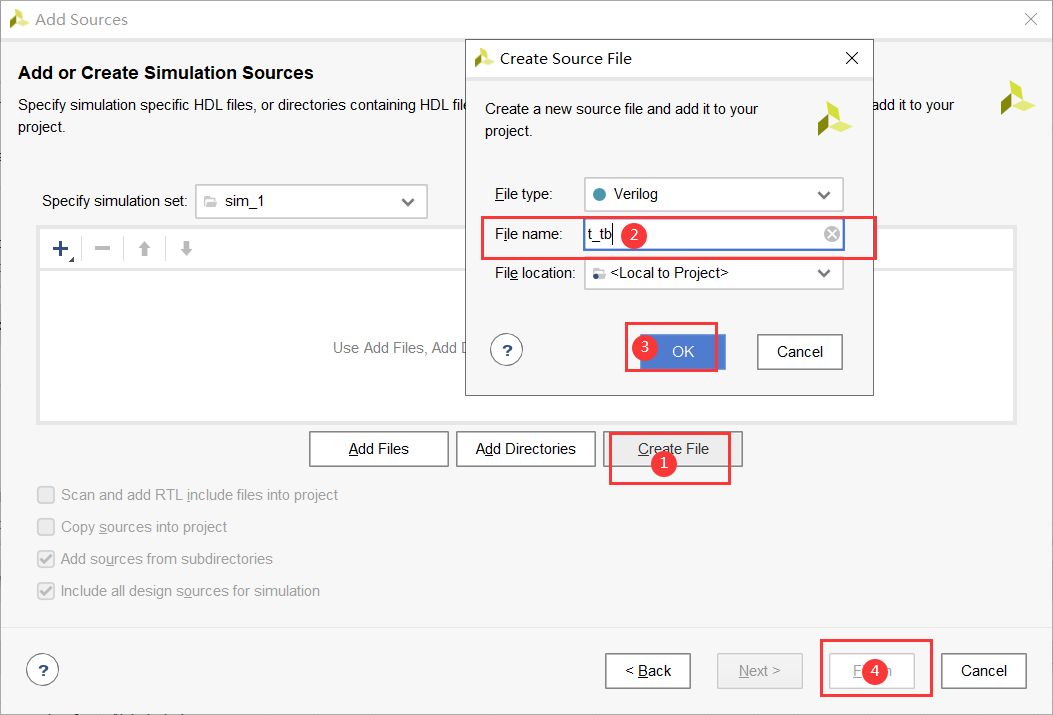
OK:
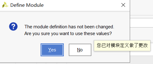
Yes:
2. 编写文件
打开文件:
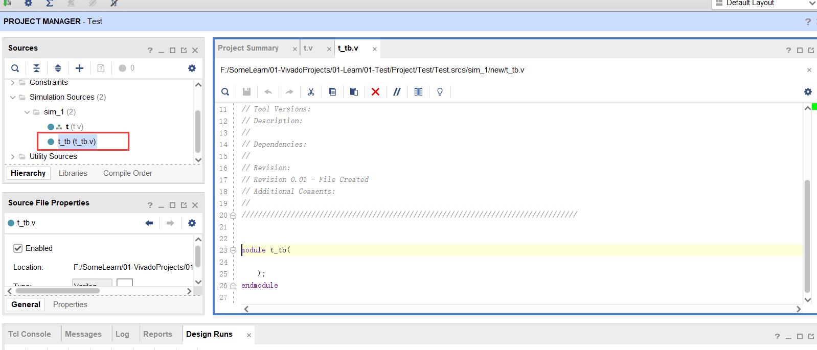
编写:
`timescale 1ns / 1ps
//
// Company:
// Engineer:
//
// Create Date: 2022/09/10 16:48:54
// Design Name:
// Module Name: t_tb
// Project Name:
// Target Devices:
// Tool Versions:
// Description:
//
// Dependencies:
//
// Revision:
// Revision 0.01 - File Created
// Additional Comments:
//
//


module t_tb(

    );

    parameter   CYCLE   =   20;

    reg     clk;

    reg     a;
    reg     b;

    wire    c;
    wire    d;
    wire    e;
    wire    f;


    always #(CYCLE / 2) clk = ~clk;

    initial begin
        clk = 0;
        a = 1'b0;
        b = 1'b0;
        repeat(10) begin
            a = {

    $random};
            b = {

    $random};
            # (CYCLE * 5);
        end

        $finish;
    end


    t t_t(
       /*input   wire*/  .a(a),
       /*input   wire*/  .b(b),

       /*output  wire*/  .c(c),
       /*output  wire*/  .d(d),
       /*output  wire*/  .e(e),
       /*output  wire*/  .f(f)
    );

endmodule
四、仿真
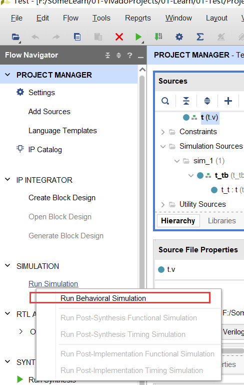
1. 运行仿真
运行仿真:
查看仿真波形:
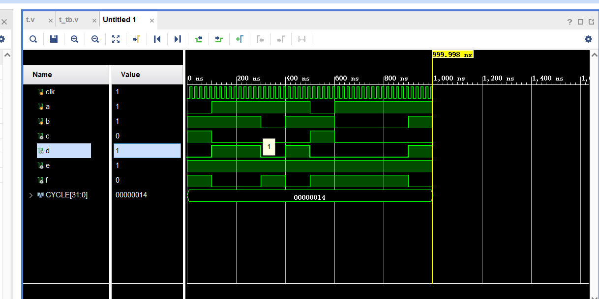
2. 仿真波形操作
| 按键 | 操作 |
|---|---|
| I | 扩大 |
| O | 缩小 |
| Shift + 鼠标滚轮 | 左右移动 |
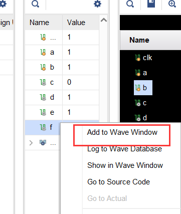
右击添加波形:
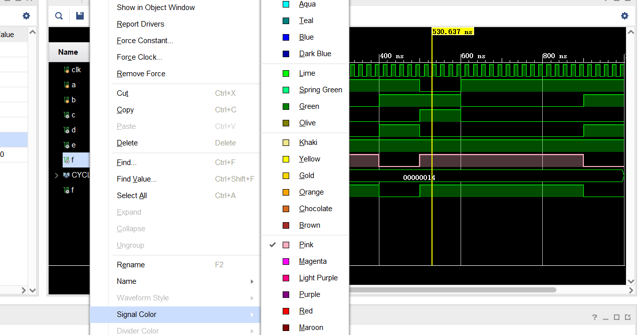
改变波形颜色:
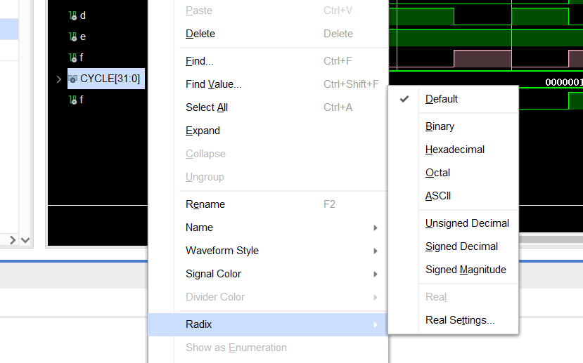
修改进制表示:
一些快捷键
| 按键 | 功能 |
|---|---|
| CTRL + D | 复制光标所在行 |
| CTRL + / | 单行注释 |
| CTRL + SHITF + / | 多行注释 |
参考
CTRL + D | 复制光标所在行 |
| CTRL + / | 单行注释 |
| CTRL + SHITF + / | 多行注释 |