在此,首先感谢CSDN的无痕幽雨,他的博客给了我很大的启发,贴上他博客的网址:https://blog.csdn.net/wuhenyouyuyouyu/article/details/52585835
我的学习总是断断续续的,学了半年STM32后又转去做FPGA,学了一年FPGA后又回来用STM32,以前对单片机的概念是用来做些简单的事情,最重要的是能够配置好寄存器驱动外设,但是现在拿起来做机械臂的控制时,我立马懵掉了,机械臂这么多个姿态,要想自动抓取那么动作必然是跟随一定流程的,特殊的动作,如果简单的驱动外设很明显无法完成这个艰巨的任务,除此以外,要想接收PYNQ串口发来的指令,这些指令能够告诉我的STM32什么时候开始抓,目标转向角是多少,目标位置是多少,等等。我们以前做仪器常用的是SPI,通过先写地址再写数据的方式非常容易修改寄存器变量,可是串口,就只能自己制造协议了,根据队友的提醒以及做FPGA的知识,我采用了状态机的写法(C语言版),最终实现了这个自定义的串口协议,并且让自己的C水平提高了一些。
废话不多说了,本次要写的代码流程图如下所示:
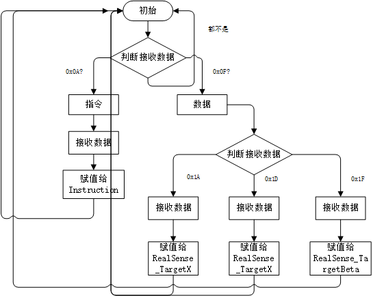
当然了,这个是我比赛串口的流程图,最终我整理出来的代码是重新写的,因此赋值有所不同。
对于嵌入式来说,外设的驱动是基本功,在这里我驱动了UART1来编写我的协议,并驱动了RGB灯进行验证, 在这里直接贴出我的驱动代码:
<LED.h>
#ifndef INC_LED_H_
#define INC_LED_H_

#include "stm32f10x.h"
#include "stm32f10x_conf.h"

#define LED_Pin_Port      GPIOB
#define LED_Green_Pin     GPIO_Pin_0
#define LED_Blue_Pin       GPIO_Pin_1
#define LED_Red_Pin        GPIO_Pin_5

#define LED_Green_ON    GPIO_ResetBits(LED_Pin_Port,LED_Green_Pin)
#define LED_Green_OFF    GPIO_SetBits(LED_Pin_Port,LED_Green_Pin)

#define LED_Blue_ON        GPIO_ResetBits(LED_Pin_Port,LED_Blue_Pin)
#define LED_Blue_OFF    GPIO_SetBits(LED_Pin_Port,LED_Blue_Pin)

#define LED_Red_ON        GPIO_ResetBits(LED_Pin_Port,LED_Red_Pin)
#define LED_Red_OFF        GPIO_SetBits(LED_Pin_Port,LED_Red_Pin)

void LED_Init(void);

#endif /* INC_LED_H_ */
<LED.c>
#include "LED.h"

void LED_Init(void)
{
    GPIO_InitTypeDef GPIO_InitStructure;

    RCC_APB2PeriphClockCmd(RCC_APB2Periph_GPIOB,ENABLE);
    GPIO_InitStructure.GPIO_Pin = LED_Green_Pin;
    GPIO_InitStructure.GPIO_Mode = GPIO_Mode_Out_PP;
    GPIO_InitStructure.GPIO_Speed = GPIO_Speed_50MHz;
    GPIO_Init(LED_Pin_Port,&GPIO_InitStructure);

    GPIO_InitStructure.GPIO_Pin = LED_Blue_Pin;
    GPIO_Init(LED_Pin_Port,&GPIO_InitStructure);

    GPIO_InitStructure.GPIO_Pin = LED_Red_Pin;
    GPIO_Init(LED_Pin_Port,&GPIO_InitStructure);
}
<uart.h>
#ifndef INC_UART_H_
#define INC_UART_H_

#include "stm32f10x.h"
#include "stm32f10x_conf.h"

void Uart1_Init(void);
void Uart1_SendByte(u8 Data);
u8   Uart1_ReceiveByte(void);
void Uart1_SendString(char *str);

#endif /* INC_UART_H_ */
<uart.c>
#include "uart.h"

void Uart1_Init(void)
{
    GPIO_InitTypeDef    Uart_GPIO_InitStructure;
    USART_InitTypeDef    Uart1_InitStructure;
    NVIC_InitTypeDef    NVIC_InitStructure;

    RCC_APB2PeriphClockCmd(RCC_APB2Periph_USART1|RCC_APB2Periph_GPIOA,ENABLE);
    Uart_GPIO_InitStructure.GPIO_Pin = GPIO_Pin_9;
    Uart_GPIO_InitStructure.GPIO_Mode = GPIO_Mode_AF_PP;
    Uart_GPIO_InitStructure.GPIO_Speed = GPIO_Speed_50MHz;
    GPIO_Init(GPIOA,&Uart_GPIO_InitStructure);

    Uart_GPIO_InitStructure.GPIO_Pin = GPIO_Pin_10;
    Uart_GPIO_InitStructure.GPIO_Mode = GPIO_Mode_IN_FLOATING;
    Uart_GPIO_InitStructure.GPIO_Speed = GPIO_Speed_50MHz;
    GPIO_Init(GPIOA,&Uart_GPIO_InitStructure);

    Uart1_InitStructure.USART_BaudRate = 115200;
    Uart1_InitStructure.USART_HardwareFlowControl = USART_HardwareFlowControl_None;
    Uart1_InitStructure.USART_Mode = USART_Mode_Rx|USART_Mode_Tx;
    Uart1_InitStructure.USART_Parity = USART_Parity_No;
    Uart1_InitStructure.USART_StopBits = USART_StopBits_1;
    Uart1_InitStructure.USART_WordLength = USART_WordLength_8b;
    USART_Init(USART1,&Uart1_InitStructure);

    NVIC_PriorityGroupConfig(NVIC_PriorityGroup_4);
    NVIC_InitStructure.NVIC_IRQChannel = USART1_IRQn;
    NVIC_InitStructure.NVIC_IRQChannelCmd = ENABLE;
    NVIC_InitStructure.NVIC_IRQChannelPreemptionPriority = 0;
    NVIC_InitStructure.NVIC_IRQChannelSubPriority = 1;
    NVIC_Init(&NVIC_InitStructure);

    USART_ITConfig(USART1,USART_IT_RXNE,ENABLE);
    USART_Cmd(USART1,ENABLE);
}

void Uart1_SendByte(u8 Data)
{
    USART_SendData(USART1,Data);
    while(USART_GetFlagStatus(USART1,USART_FLAG_TXE) == RESET);
}

void Uart1_SendString(char *str)
{
    while((*str)!='\0')
    {
        Uart1_SendByte(*str);
        str++;
    }
    while(USART_GetFlagStatus(USART1,USART_FLAG_TC) == RESET);
}

u8   Uart1_ReceiveByte(void)
{
    u8 Receive_Data;
    Receive_Data = USART_ReceiveData(USART1);
//    while(USART_GetFlagStatus(USART1,USART_FLAG_RXNE) == RESET);
    return Receive_Data;
}
到了这里,就能够驱动好我的串口1和LED灯了,接下来就是重点所在FSM
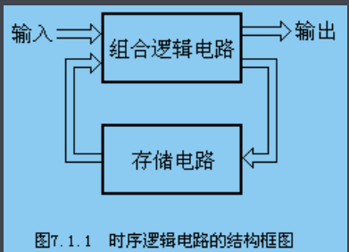
盗个图,这个就是时序逻辑电路的经典结构框图,因此使用Verilog描述状态机的时候,我都喜欢使用三段式状态机,因为它有这个味道,很好地反映了时序逻辑电路的结构,而一段式状态机如果不是Verilog的并行态,它早没了,而到了C语言,emm,本来就是顺序执行的,就会有一些问题,比如这样:
if(state == Idle)
{
    ........
}
else if(state == State1)
{
    ........
}
else if(state == State2)
{
    ........
}
else
{
    .........
}
众所周知,C语言的if else if语句是从第一条开始判断的,如果符合条件的那一行永远在后面几行,那么就要每次多执行很多次的if .....而if是判断语句,括号内是要执行运算的,即使是单周期指令的MCU,在进行乘除运算等都需要消耗多个时钟周期,因此,每次多执行1次判断至少浪费一个时钟周期甚至更多,因此,这样子的状态机无疑是效率低下的,恐怖的是,网上一大堆所谓的C语言状态机都是采用这种做法,让我一开始也蒙圈了很久。
后来我还看到一个贴子,qiuri2008的https://www.cnblogs.com/jiangzhaowei/p/9129024.html,他的FSM在原来的基础上做了一点改进,使用了结构体封装每一个状态的信息,并且使用了函数指针的方式进行构造状态机的核,我在模仿它的代码的时候感觉到了进步但是还是很疑惑,这样和我上述所说的有区别吗?
盗用一下他的代码:
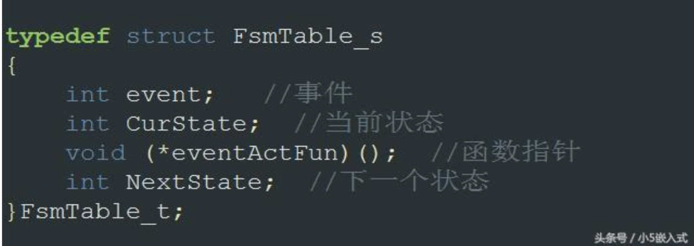
这一段相当于定义了一个数据控制块,类似于OS中的TCB
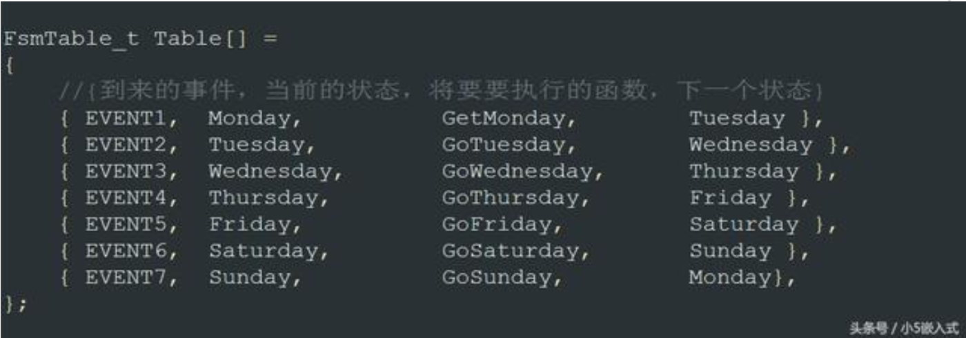
而这里则利用数组构成了一个数据控制块的表,记录着状态机的信息
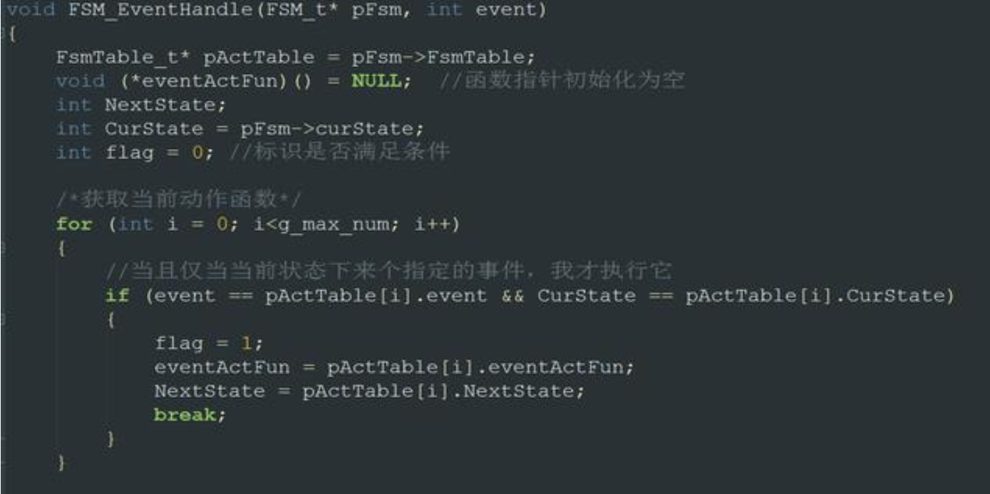
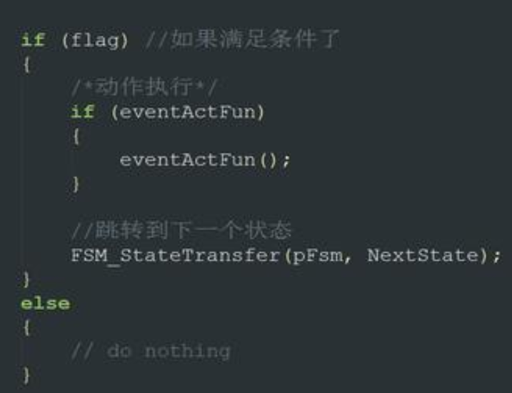
好的,这个就是他的核心代码啦,还是很值得学习的,这个是状态机的思想,用一个表来存储状态信息,并通过组合逻辑来判断状态是否跳转,通过函数指针来执行函数,就可以在不同的状态下执行不同的函数了。可是我模仿它的代码写的时候,却发现了一样致命的事情——Event!
从表中可以看到,当前状态相同而下一状态不同的EVENT是不一样的值,既然如此,根据状态机的定义,要判断EVENT是什么就需要这样写:
void EventJudge(u8 ReceiveData)
{
      switch(CurState)
     {
          case Idle: if(ReceiveData == '1')
                           .....
                         else
                             ......
          case State1: if(ReceiveData == '2'))
                          .......
           default: ......
     }
}
那么这样子写的意义又何在呢?加上之前的For查找Event并且比对,其实这样子写效率什么还没有直接的if else if高呢
而CSDN的无痕幽雨却这样构造状态机核:
typedef State(*Procedure)(void*);
Procedure Steps[] = {Idle_Fun , State1_Fun.......};
typedef struct{
  u8 Target1;
  u8 Target2;
}SM_Arg_T
void BestStateMachine(void * invar)
{
    static State NS = s_init; //定义下一状态
    NS = Steps[NS](invar);
}
这里采用函数内static,静态局部变量,这样做可以让函数每一次重新进入该函数的时候使用上一次修改的值,类似于全局变量,有利于函数模块化。而使用函数指针数组则可以直接通过索引找到对应函数,因此,若我们每一个状态的函数返回一个状态参量,那么就可以直接索引至对应的函数指针,这样的查找表方式,相较于for循环查找表可谓快了很多很多倍,因此,每一个状态函数都应该这样写
State Uart_Idle_Fun(void *arg)
{
    Uart_SM_Arg_t* Uart_SM_Arg = (Uart_SM_Arg_t*)arg;
    if(Uart_SM_Arg->ReceiveData == 0xAA)
    {
        return Type_Judge;
    }
    else
    {
        return Uart_Idle;
    }
}
注意这里的入口参数,采用指针当入口参数,这样子函数内就可以很方便的修改以及读取参数,并且不用占用大量的栈空间,FreeRTOS的邮箱也是一样的道理,使用了消息队列,也是传的指针,而不是传一大块数据
最后,贴下自己的FSM代码实现吧
<UART1_FSM.h>
#ifndef INC_UART1_FSM_H_
#define INC_UART1_FSM_H_

#define Instruction_Type    1
#define Data_Type            2

#include "uart.h"

typedef u8 State;
enum{
    Uart_Idle,
    Type_Judge,
    InstructionAssignment,
    DataAttributionJudge,
    DataAssignment
};
typedef State(*Uart_Procedure)(void*);
typedef struct{
    u8    ReceiveData;
    u8    Type;
    u8    Instruction;
    u8     DataAttribution;
    u8    Data;
}Uart_SM_Arg_t;

State Uart_Idle_Fun(void *arg);
State Uart_Type_Judge_Fun(void* arg);
State Uart_InstructionAssignment_Fun(void* arg);
State Uart_DataAttributionJudge_Fun(void* arg);
State Uart_DataAssignment_Fun(void* arg);
void UartStateMachine(Uart_SM_Arg_t *arg);

extern Uart_SM_Arg_t    Uart1_SM_Arg;
extern u8 Target1,Target2,Target3;

#endif /* INC_UART1_FSM_H_ */
<UART1_FSM.c>
#include "UART1_FSM.h"

u8 Target1,Target2,Target3;


Uart_Procedure Uart_Steps[] = { Uart_Idle_Fun, Uart_Type_Judge_Fun, Uart_InstructionAssignment_Fun, Uart_DataAttributionJudge_Fun, Uart_DataAssignment_Fun};

Uart_SM_Arg_t    Uart1_SM_Arg ={
        .Data = 0,
        .DataAttribution = 0,
        .Instruction = 0,
        .ReceiveData = 0,
        .Type = 0
};

State Uart_Idle_Fun(void *arg)
{
    Uart_SM_Arg_t* Uart_SM_Arg = (Uart_SM_Arg_t*)arg;
    if(Uart_SM_Arg->ReceiveData == 0xAA)
    {
        return Type_Judge;
    }
    else
    {
        return Uart_Idle;
    }
}

State Uart_Type_Judge_Fun(void* arg)
{
    Uart_SM_Arg_t* Uart_SM_Arg = (Uart_SM_Arg_t*)arg;
    if(Uart_SM_Arg->ReceiveData == 0x0A)
    {
        Uart_SM_Arg->Type = Instruction_Type;
        return InstructionAssignment;
    }
    else if(Uart_SM_Arg->ReceiveData == 0x0F)
    {
        Uart_SM_Arg->Type = Data_Type;
        return DataAttributionJudge;
    }
    else
    {
        return Uart_Idle;
    }
}

State Uart_InstructionAssignment_Fun(void* arg)
{
    Uart_SM_Arg_t* Uart_SM_Arg = (Uart_SM_Arg_t*)arg;
    if(Uart_SM_Arg->Type == Instruction_Type)
    {
        Uart_SM_Arg->Instruction = Uart_SM_Arg->ReceiveData;
        return Uart_Idle;
    }
    else
    {
        return Uart_Idle;
    }
}

State Uart_DataAttributionJudge_Fun(void* arg)
{
    Uart_SM_Arg_t* Uart_SM_Arg = (Uart_SM_Arg_t*)arg;
    if(Uart_SM_Arg->Type == Data_Type)
    {
        Uart_SM_Arg->DataAttribution = Uart_SM_Arg->ReceiveData;
        return DataAssignment;
    }
    else
    {
        return Uart_Idle;
    }
}

State Uart_DataAssignment_Fun(void* arg)
{
    Uart_SM_Arg_t* Uart_SM_Arg = (Uart_SM_Arg_t*)arg;
    if(Uart_SM_Arg->DataAttribution == 0xA1)
    {
        Uart_SM_Arg->Data = Uart_SM_Arg->ReceiveData;
//        Uart_SM_Arg->MachineBi.RealSense_Target.RealSense_TargetBeta = Uart_SM_Arg->Data;
        Target1 = Uart_SM_Arg->Data;
        return Uart_Idle;
    }
    else if(Uart_SM_Arg->DataAttribution == 0xA2)
    {
        Uart_SM_Arg->Data = Uart_SM_Arg->ReceiveData;
//        Uart_SM_Arg->MachineBi.RealSense_Target.RealSense_TargetX = Uart_SM_Arg->Data;
        Target2 = Uart_SM_Arg->Data;
        return Uart_Idle;
    }
    else if(Uart_SM_Arg->DataAttribution == 0xA3)
    {
        Uart_SM_Arg->Data = Uart_SM_Arg->ReceiveData;
//        Uart_SM_Arg->MachineBi.RealSense_Target.RealSense_TargetY = Uart_SM_Arg->Data;
        Target3 = Uart_SM_Arg->Data;
        return Uart_Idle;
    }
    else
    {
        return Uart_Idle;
    }
}

void UartStateMachine(Uart_SM_Arg_t *arg)
{
    static State Next_State = Uart_Idle;
    Next_State = Uart_Steps[Next_State](arg);
}
验证代码
int main(void)
{
  Uart1_Init();
  LED_Init();
  /* TODO - Add your application code here */

  /* Infinite loop */
  while (1)
  {
      if(Target1 == 0xA0)
      {
          LED_Red_ON;
          LED_Green_OFF;
          LED_Blue_OFF;
      }
      else if(Target2 == 0x0F)
      {
          LED_Red_OFF;
          LED_Green_ON;
          LED_Blue_OFF;
      }
      else
      {
          LED_Red_OFF;
          LED_Green_OFF;
          LED_Blue_ON;
      }
  }
}
初始状态:
串口调试助手输入:
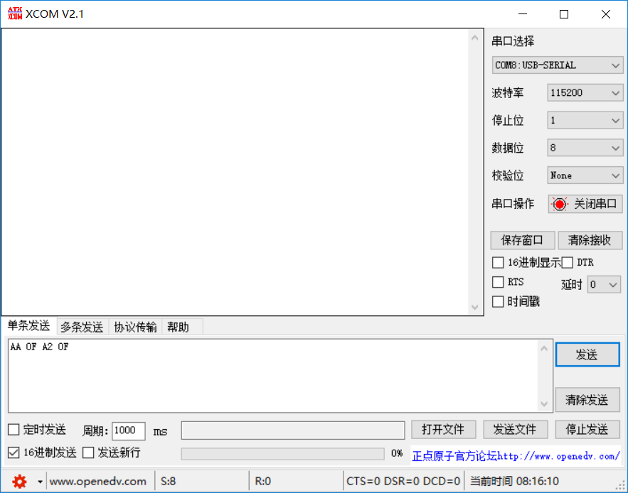
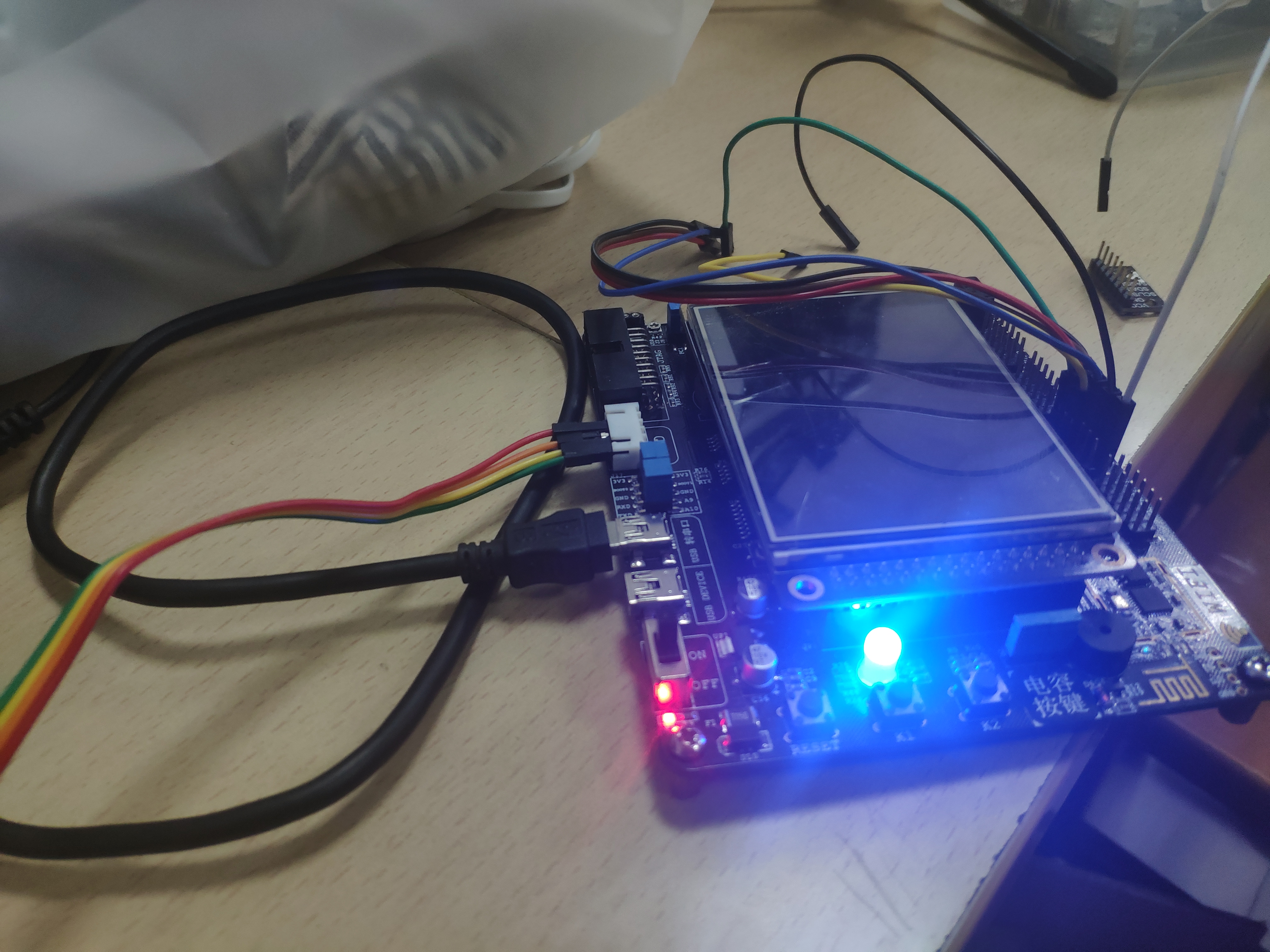
实验现象:
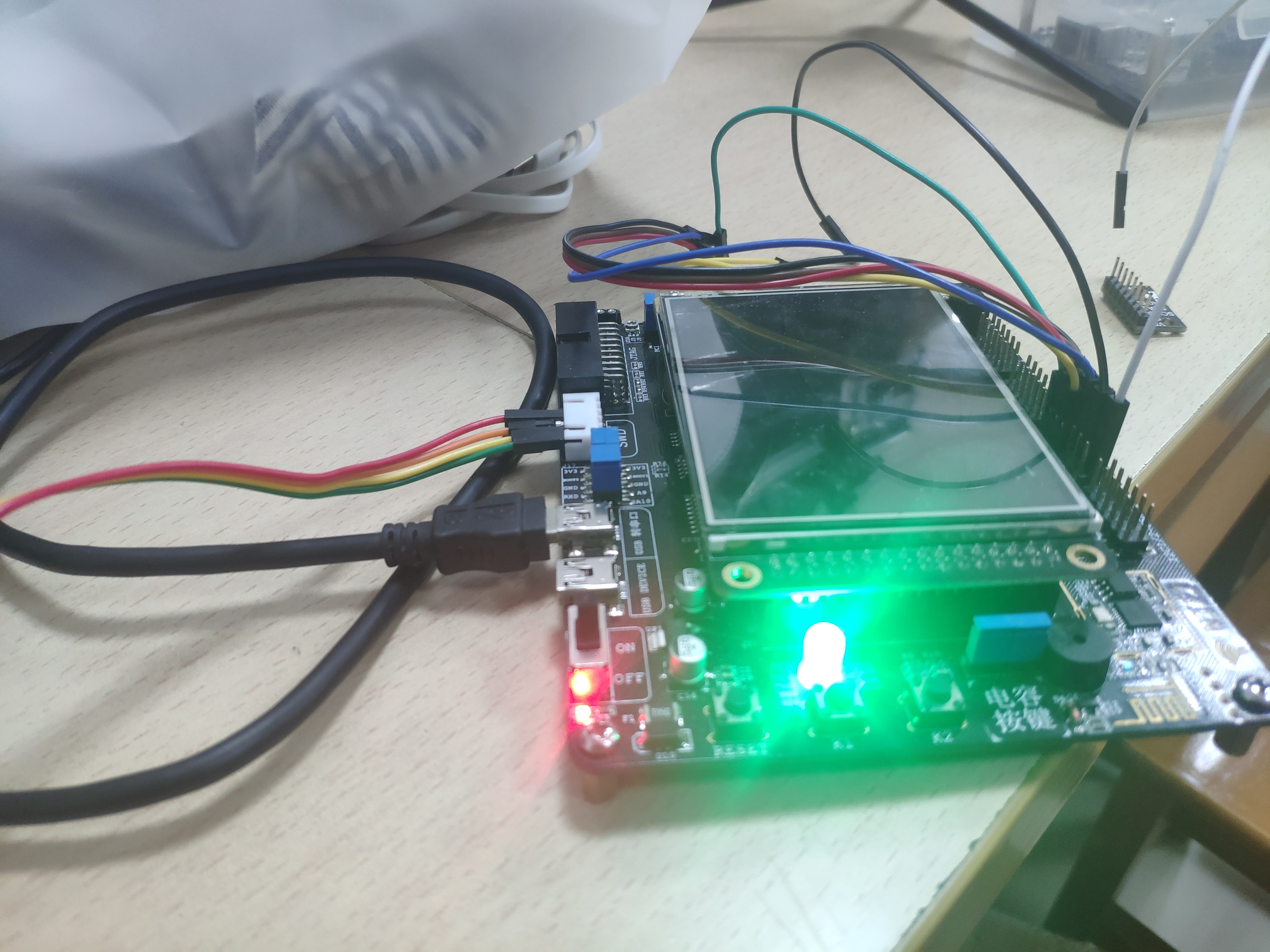
大功告成!