前言:
由于2018年Robocn的比赛不可以使用激光,超声等,具有可以通讯的可疑设备,然而有需要全场定位这种要求,所以不得不采用视觉方案!然而其中最基础的就是解决相机的标定问题!接下来介绍Matlab 进行相机标定的流程操作!
这种标定的方式在网上有很多的公式啊,原理讲解,这里只是在应用上进行介绍!
当然了,还是需要简单了解下标定基础知识的:
点击打开链接
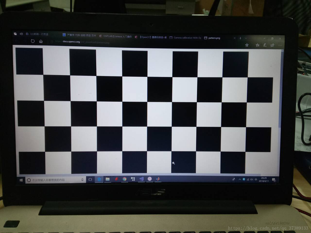
首先就是进行标定板的图像采集
对于标定板,由于时间有限,就不采用打印的方式了,我直接在网页上显示!环保绿色!
标定嘛,肯定需要具体尺寸样标的,所以我直接在电脑上量取,这个误差在小范围内可以允许!
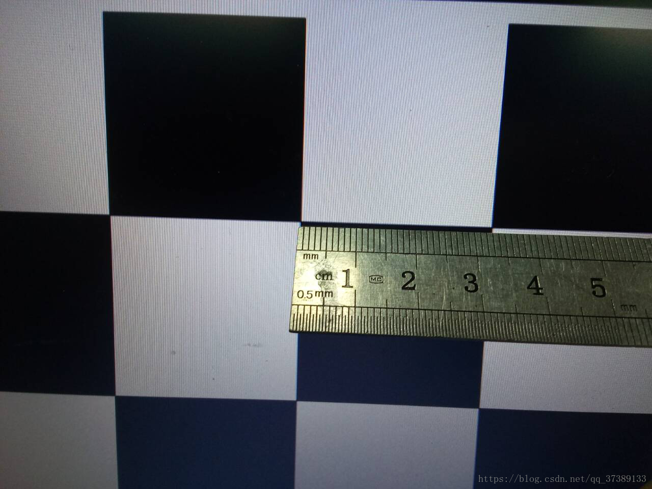
如你所见我测的数据是33mm,这里的数据等会在Matlab的 Camera Calibrator是要使用的!
这里附上OpenCV简单的图片采集程序,按‘q' 获取,按esc退出!
#include "opencv2/opencv.hpp"
#include <string>
#include <iostream>


using namespace cv;
using namespace std;

int main()
{
	VideoCapture inputVideo(0);
	inputVideo.set(CV_CAP_PROP_FRAME_WIDTH, 800);
	inputVideo.set(CV_CAP_PROP_FRAME_HEIGHT, 600);
	if (!inputVideo.isOpened())
	{
		cout << "Could not open the input video " << endl;
		return -1;
	}
	Mat frame;
	string imgname;
	int f = 1;
	while (1) //Show the image captured in the window and repeat
	{
		inputVideo >> frame;              // read
		if (frame.empty()) break;         // check if at end
		imshow("Camera", frame);
		char key = waitKey(1);
		if (key == 27)break;
		if (key == 'q' || key == 'Q')
		{
			imgname = to_string(f++) + ".jpg";
			imwrite(imgname, frame);
		}
	}
	cout << "Finished writing" << endl;
	return 0;
}
注意这里inputVideo.set(CV_CAP_PROP_FRAME_WIDTH, 800);
inputVideo.set(CV_CAP_PROP_FRAME_HEIGHT, 600);
如果没有设置,OpenCV直接按默认大小的获取图像尺寸!
如果没有设置,OpenCV直接按默认大小的获取图像尺寸!
接下来就是进行多角度的拍摄,角度越丰富越好!

因为我是VS2017,且没有规定路径,所以图片直接存储在项目文件夹中!
MATLAB操作
如下图找到
Camera Calibrator
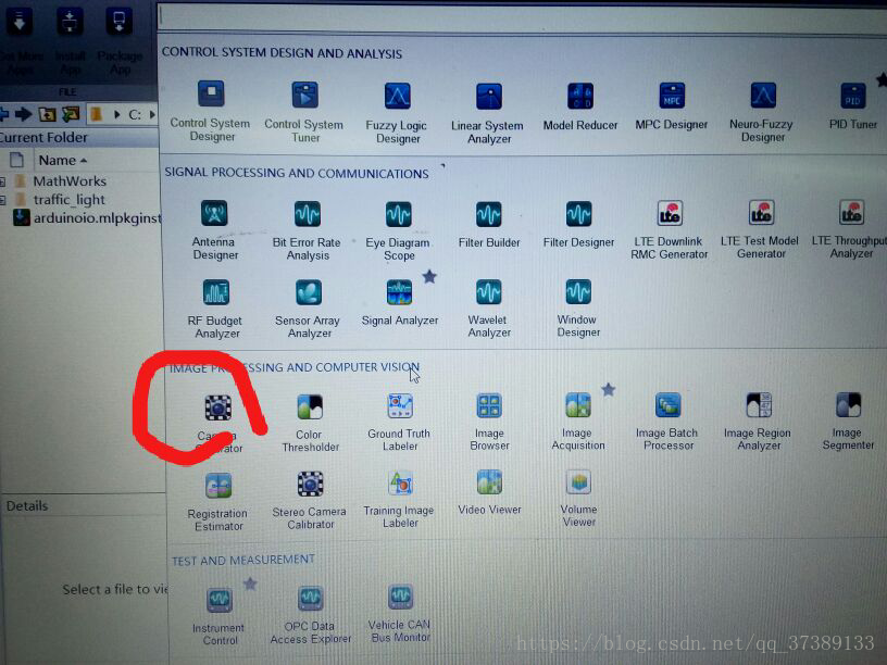
运行可以看到
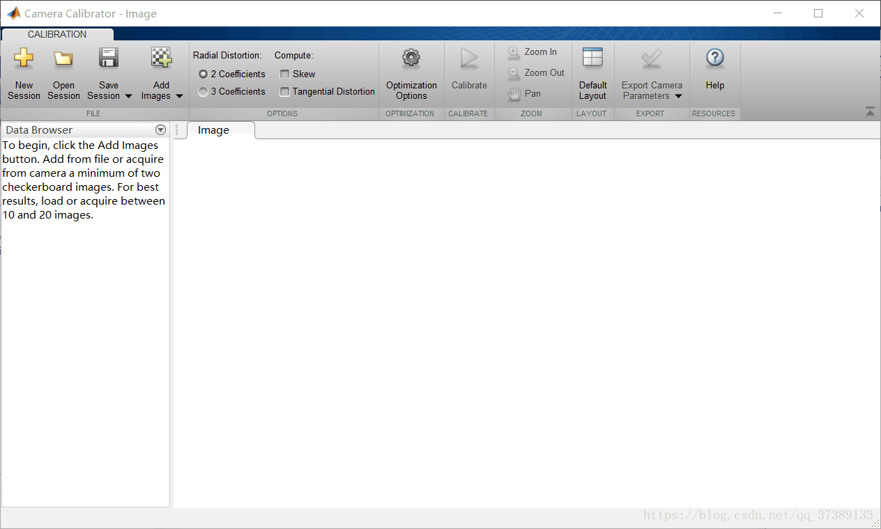
点击Add Images时,会显示:

注意这里是要输入黑白正方体的大小的,在上面的测定中,显示的是33mm,所以这里填写33
注意这里的图片还是要多一点:

然后选定以下参数:
为了防止可能产生极大的扭曲,所以选择使用两参数,并且选择错切和桶形畸变。
 直接点击Calibrate 就可以了
然后保存Camera Parameters就可以了
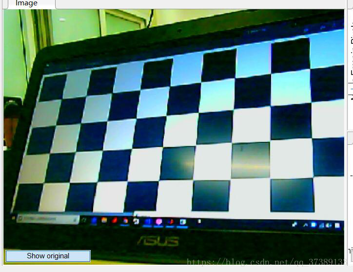
这是矫正前的图片:

点击show Undistorted即可看到校正后的图像:
数据分析:
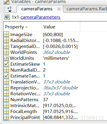
白畸变参数,总共有五个,径向畸变3个(k1,k2,k3)和切向畸变2个(p1,p2)。
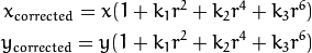
径向畸变:
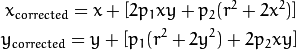
切向畸变:
以及在OpenCV中的畸变系数的排列(这点一定要注意k1,k2,p1,p2,k3)。

径向畸变:
切向畸变:
以及在OpenCV中的畸变系数的排列(这点一定要注意k1,k2,p1,p2,k3)。
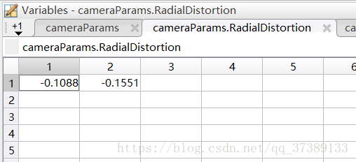
对应 k1 k2 k3由于前面选择 ,所以这里就为0
,所以这里就为0
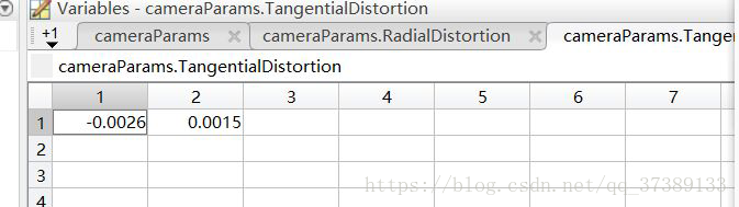 对应 p1 p2
对应
矫正代码示例:
#include "opencv2/opencv.hpp"
#include <string>
#include <iostream>
using namespace cv;
using namespace std;
int main()
{
VideoCapture inputVideo(1);
inputVideo.set(CV_CAP_PROP_FRAME_WIDTH, 800);
inputVideo.set(CV_CAP_PROP_FRAME_HEIGHT, 600);
if (!inputVideo.isOpened())
{
cout << "Could not open the input video: " << endl;
return -1;
}
Mat frame;
Mat frameCalibration;
inputVideo >> frame;
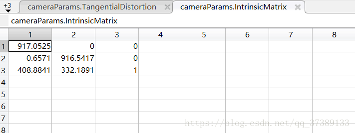
Mat cameraMatrix = Mat::eye(3, 3, CV_64F);
cameraMatrix.at<double>(0, 0) = 917.052472085750;
cameraMatrix.at<double>(0, 1) = 0.657056681717874;
cameraMatrix.at<double>(0, 2) = 408.884053678499;
cameraMatrix.at<double>(1, 1) = 916.541676777971;
cameraMatrix.at<double>(1, 2) = 332.189066871859;
Mat distCoeffs = Mat::zeros(5, 1, CV_64F);
distCoeffs.at<double>(0, 0) = -0.108750634204250;
distCoeffs.at<double>(1, 0) = -0.155068804309725;
distCoeffs.at<double>(2, 0) = -0.00261486335789016;
distCoeffs.at<double>(3, 0) = 0.00154770538482982;
distCoeffs.at<double>(4, 0) = 0;
Mat view, rview, map1, map2;
Size imageSize;
imageSize = frame.size();
initUndistortRectifyMap(cameraMatrix, distCoeffs, Mat(),
getOptimalNewCameraMatrix(cameraMatrix, distCoeffs, imageSize, 1, imageSize, 0),
imageSize, CV_16SC2, map1, map2);
while (1) //Show the image captured in the window and repeat
{
inputVideo >> frame; // read
if (frame.empty()) break; // check if at end
remap(frame, frameCalibration, map1, map2, INTER_LINEAR);
imshow("Origianl", frame);
imshow("Calibration", frameCalibration);
char key = waitKey(1);
if (key == 27 || key == 'q' || key == 'Q')break;
}
return 0;
}
以上为OpenCV提供的简单 代码示例!
以下为原来的图像:
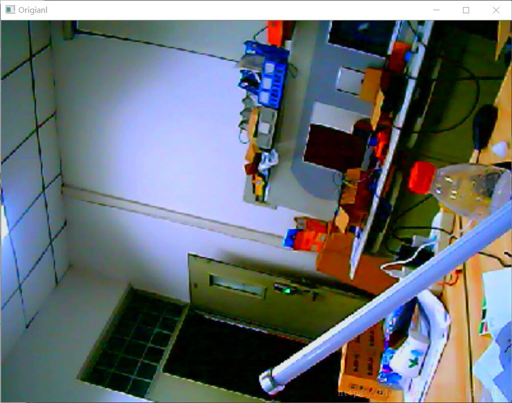
以下为矫正后的图像:

以上为基本的操作流程,可见Matlab 是有多么的强大!
至于矫正后对于那个黑色区域怎么办呢? 可以直接矩形框选中间区域就行了。
相机无畸变后,我们就可以把真实世界的坐标,直接转化为图像里的坐标! 依据像素做有意思的事情! 例如我曾经利用几何原理做过扫描线激光的三维重建! 这个原理也就是现在市面上的短距离激光雷达的基本结构,区别就是,我是三维的!
有误希望指点!